AERODYNAMICS AND THEORY OF FLIGHT
- AERODYNAMICS AND THEORY OF FLIGHT
Forces of Flight
Lift
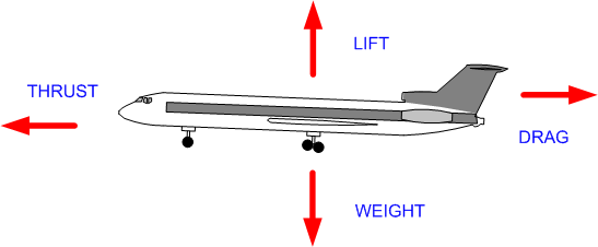
Lift is an artificial force manipulated by pilot; it is generated through the wings, acts perpendicular to the relative wind and wingspan. The theoretical concept that summarizes the direction and force of lift is the centre of pressure. Lift opposes weight—during level cruise, lift equals weight; during climb, lift is greater than weight; and during descent, weight is greater that lift.
Weight
Weight is a natural (uncontrollable) force generated by gravity (g force) that acts perpendicular to earth’s surface; theoretically, weight is exerted through the centre of gravity, and opposes lift.
Thrust
Thrust is an artificial force manipulated by pilot and generated through engine(s) that acts horizontally, parallel to flight path; thrust opposes drag—when airspeed constant, thrust equals drag; when airspeed accelerating, thrust is greater than drag; and when decelerating, drag is greater than thrust.
Drag
Drag is the natural resistance of an aeroplane while it is moving through air; it is partially controlled by pilot. Drag is a horizontal force acting parallel to flight path, and is opposed to thrust.
Generating Lift
Airfoils

As viewed as a cross-section, the upper surface of an airfoil has more camber (curve) than lower surface. A straight line from leading edge to trailing edge is referred to as the chord. With this structure, lift is generated by two process—what are referred to as pressure differential and ram air.
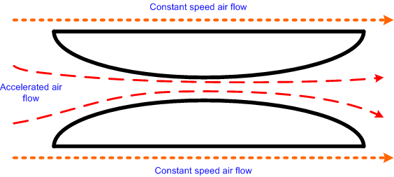
Lift by pressure differential is based on the theory of Daniel Bernoulli (Bernoulli’s Theorem)—the faster a fluid flows (including air), the lower will be the pressure surrounding it; given the difference of the camber of the upper and lower surfaces, the air passing over the foil has greater distance to travel than the air passing under the airfoil; the air passing over must therefore travel faster than the air passing under the foil; a low air-pressure region is created above the accelerated air flow; the foil is displaced toward the lower pressure (upward) above the wing. This pressure differential accounts for about 50% of the lift, while the remaining lift is generated by ram air. With ram air, air is rammed under the foil, creating downwash and resultant upward pressure—this is based on Isaac Newton’s Third Law (the application of force causes an equal opposite force).
Angle of Attack

Lift varies with the angle of attack—the angle between the relative wind (parallel to flight path) and the chord line (line between leading and trailing edge). Generally, the greater the angle of attack, the greater the lift—lift increases because the distance the air must flow along the upper camber increases, and the ram air and downwash increase. An excessive angle of attack, referred to as the critical angle of attack (usually about 20°) will produce a stalled condition—laminar airflow above the wing is displaced by turbulent airflow, and differential pressure collapses.
Parasitic Drag
Parasitic drag is drag created by those parts of an aeroplane that do not contribute to lift—e.g., the tires, windshield, rivets, etc. There are, in turn, three forms of parasitic drag—form drag, skin-friction drag, and interference drag. Form drag is caused by the frontal areas of the aeroplane, and is reduced by streamlining. Skin-friction drag is caused by the air passing over the aeroplane surfaces, and is reduced by smoothing the surfaces (flush riveting, smooth paints, and waxing). Interference drag is caused by the interference of airflow between parts of an aeroplane (wings and fuselage or fuselage and empennage) and is reduced by filleting interference areas.
Induced drag
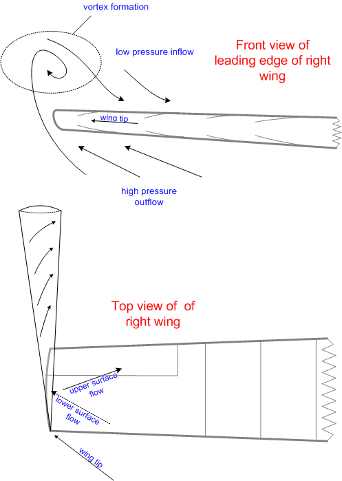
Induced drag is created by those parts of the aeroplane that create lift—the wings and the horizontal tail surface; induced drag is said to be the by-product or cost of lift—that is, the greater the angle of, attack, the greater the induced drag. Induced drag does not increase with speed; instead, as speed decreases induced drag increases.
Induced drag is associated with difference in pressure that exists above and below a wing surface—as airspeed decreases, an airfoil must produce an increased low pressure above the wing, and an increased high pressure below the wing. At the wingtip these disparate pressures meet in the form of a vortex as the high pressure flow around the wingtip is sucked into the low pressure above the wing; the greater the pressure differences (such as in the case in slower flight), the greater the vortices are at each wing tip, and the greater the drag caused by these vortices.1
Ground Effect
Ground effect is a term used to describe the reduced drag and increased lift experience when an aircraft is flying close to the ground—as is the case, for example, during landings and takeoffs; the reduce drag associated with ground effect is the result of the ground interfering with the formation of the wingtip vortices. Ground effect exists when the aircraft is within one wingspan distance from the ground, but is most effective at distances equal or less than ½ wingspan (i.e., ½ the distance between the wingtips).
Boundary Layer
During flight, there are two types of airflow along the upper camber of an airfoil—turbulent and laminar (smooth). Turbulent and laminar flow are separated by a point of transition or separation point; as the angle of attack is increased, the portion of the upper airflow that is turbulent also increases (it migrates forward from the trailing edge) and therefore produces increased drag.
Vortex generators are small fins (approximately 1 inch tall) that are placed along the leading edge of an air foil; the vortex generators are themselves small air foils that are placed perpendicular to the upper wing surface, and are positioned so as to meet the laminar flow coming over the wing with a slight angle attack; the vortex generators, as the name implies, generate vortices which regenerate the boundary layer and delay turbulent flow (boundary layer separation).
Stalls
Stalls occur at the critical angle of attack, where induced drag (airfoil drag) exceeds lift—the wing can no longer produce sufficient lift to counteract weight. As the airfoil approaches the critical angle of attack, the point of transition, or separation point, moves forward enough to exceed the design factor of the wing. In contrast, the centre of pressure moves forward as the angle of attack is increased until the critical angle of attack is achieved; when a stall occurs, the centre of pressure moves rearward, causing the instability associated with stall phenomena.
As said earlier, the stalling angle is usually 20°. Since most aircraft lack angle-of-attack indicators, airfoil angle is measured by indicated airspeed (IAS)—our best estimate of the actual angle of attack. As a rule, aircraft will usually stall near the stalling speed published in the Pilot Operating Handbook; however, IAS does not always accurately indicate angle of attack, as in the case of a high-speed stall.
Factors that affect the Stall
Contaminants. Snow, frost, ice and dirt—all of these disrupt the laminar flow and therefore reduce airfoil lift capability. It is illegal to fly with snow, frost, or ice adhering to critical surfaces of the aircraft—“wings, control surfaces, rotors, propellers, horizontal stabilizers, vertical stabilizers or any other stabilising surface of an aircraft (CAR 602.11).” Contamination to the extent of medium to coarse sandpaper will reduce lift by 30% and increase drag by 40%.
Weight. Increased weight requires increased lift and an increased angle of attack; therefore the critical angle of attack (stall) will occur at higher airspeeds. Stated another way, if two aircraft are travelling at the same airspeed, but one is heavier than the other, the angle of attack of the heavier aircraft is greater than the lighter aircraft and therefore that much closer to the critical angle of attack.
Centre of Gravity. Stalling speed increases as the aircraft C of G moves forward. As the C of G moves forward, the negative lift generated by the horizontal tail surface will have to be increased. Any increase in the negative lift produced by the tail will effectively increase the aerodynamic weight of the aircraft—producing the same effect as described above with respect to weight. Conversely, stalling speeds decrease as the C of G moves aft as less negative lift is required from the tail and the aircraft is aerodynamically lighter. While the benefits of a rearward C of G is a lower stall speed, the adverse result of a rearward C of G is less stability as there is less tail force that can be manipulated by the pilot through elevator or stabilator control.
Turbulence. Upward vertical gusts abruptly increase the angle of attack beyond the stalling angle, irrespective of airspeed.
Turns. During a turn in level flight, greater lift is required to offset increased load factor; the critical angle of attack is therefore reached at higher airspeeds. The formula is as follows—normal stalling speed times the square root of the load factor equals banked stall speed; accordingly, an aircraft with a stall speed of 50 KTS in a 60°-banked turn (load factor of 2.0) will stall at 71 KTS.
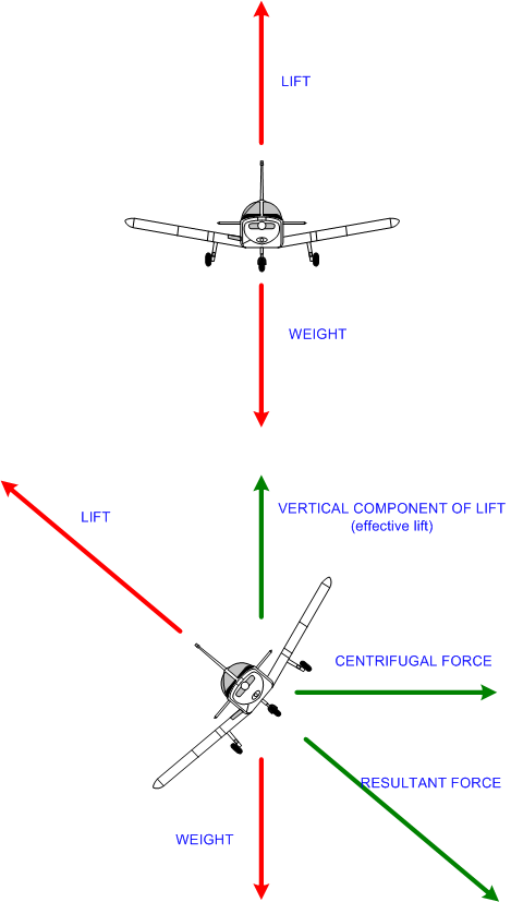
During a climbing turn, the inner wing has a smaller angle of attack than the outer wing; the outer wing will therefore stall first. The reverse is the case for descending turn, where the inner wing has a larger angle of attack and will therefore stall first.2
Flaps. An increase in airfoil lift is produced by the use of flaps, and the stall speed is decreased by their use.
Spins
Spinning is defined as autorotation that develops after an asymmetrical or aggravated stall (a wing dropping during a stall)—the downward moving wing has a higher angle of attack and more induced drag than the upward moving wing and therefore acquires a greater stalled condition. Spinning involves simultaneous roll, yaw, and pitch as it develops a helical or corkscrew path nose down. An incipient spin is the autorotation prior to a vertical descent path, while a fully developed spin begins once the vertical path is achieved.
Lift and Drag Concepts
Factors that affect lift and drag can be expressed in the following formulas:
Lift = CL × ½ pV2 × S
Drag = CD × ½ pV2 × S
In these formula,
CL = lift coefficient (angle of attack)
CD = drag coefficient
S = the plan area (or wing area) of an airfoil
V= the TAS or an aircraft’s velocity squared
p = the density of the air.
Don’t be alarmed by the esoteric appearance of these formulas. Coefficient simply means a value that is constant or predictable, and in this case it is by virtue of the shape and design of the airfoil—the coefficient (whether for drag or lift) will vary with the angle of attack of the airfoil. Therefore, think of CL or CD as “angle of attack”. Note, however, that the rest of the equation is the same for both lift and drag, and further note that air density and TAS, and wing area are concepts which you are likely already familiar with. So what is the big deal with these formulas? The answer is this: V2. Lift and drag increase exponentially with speed—if speed is doubled, drag or lift will be quadrupled. In contrast the relationship between lift or drag and air density is a direct relationship such that an increase or decrease in air density will cause an increase or decrease in both drag and lift.
The relationship between drag and speed is of special interest with respect to the concepts of flight for maximum endurance (VME) and maximum range (VMR), as well as the concept of slow flight.
As speed increases, parasitic drag increases exponentially, and as speed decreases, induced drag increases exponentially. This is referred to as the drag curve.
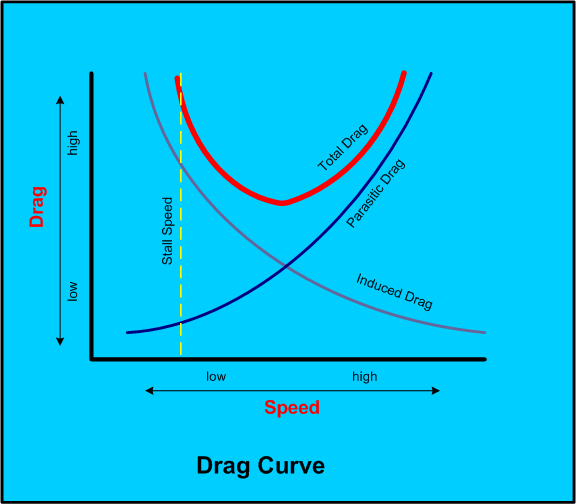
At the bottom of the drag curve—that is, the position at where drag is at the combined minimum value—is the speed for maximum range—i.e., the speed at which the maximum amount of speed (or distance) is obtained per unit of fuel.
To decrease speed from VMR would increase fuel consumption as a result of increased induced drag, while to increase speed from VMR would increase fuel consumption as a result of increased parasitic drag.
The bottom of the drag curve is the most efficient speed at which the airfoil can generate maximum lift and minimum drag—this is the speed at which you will maximum-distance glide. If you were to express lift and drag as a ratio, this position would be referred to as the maximum lift-drag ratio.
In contrast, we can also produce a curve—again relative to changes in speed—representing the minimum amount of power necessary to offset drag; this power curve would be quite similar in shape to the drag curve. The bottom of the power curve would be the maximum endurance speed (VME). If we could compare the two curves—power and drag—we would note that VME is slightly less that VMR. Flight between VME and VSO is the slow flight range.
Wing Design
Laminar and conventional airfoils

Two types of airfoils commonly used are the laminar and conventional airfoils; as a rule, the laminar foil is faster, but the cost is more adverse stalling characteristics. The two types differ with respect to location of the maximum camber—while the maximum camber on a conventional airfoil is located 25% behind the leading edge, the laminar maximum camber is located at 50% chord. On the laminar foil, a greater portion of the upper camber is dedicated to laminar airflow; there is therefore less surface friction drag. The cost of this, however, is that the transition or separation point jumps rapidly forward at the approach of a stall. Additionally, the laminar foil is more susceptible to surface contamination.
Angle of incidence
The angle of incidenceis defined as the angle between the chord line and the longitudinal axis of the aeroplane; designers select an angle that provides optimum lift/drag ratio.
Washout
Washout is a design trait that pacifies or softens the stall characteristics of an aeroplane whereby the wings are twisted such that the wing tips have a lower angle of incidence than the wing root. This means that the entire wing will not stall simultaneously; instead, the stall will progressively move from the roots to the tips. Since the wing tips are the last to stall, the ailerons will remain effective longer during the stall.
Stall Strips
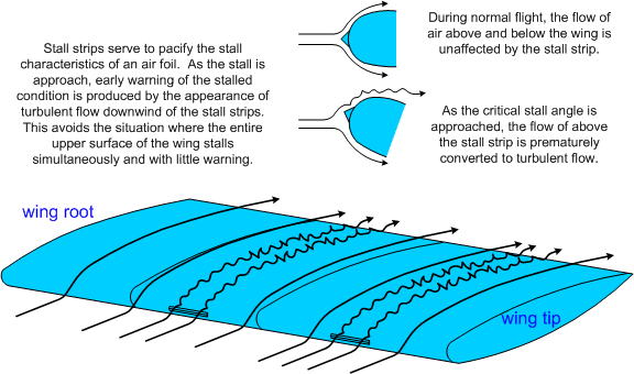
Stall strips are triangular strips placed on a portion of the leading edge of wing; they also have the effect of pacifying the stall characteristic of an aircraft—instead of the entire wing surface stalling uniformly, stall strips create a two-phase stall whereby those portions of the wing behind the strips stall first as the angle of attack is increased.
Airfoil Variation
Airfoil variation is in fact span-wise airfoil variation whereby a thin high-speed airfoil is designed near the roots, and a thick low-speed airfoil near the tips. The result is that the high-speed roots stall before the low-speed tips—again, this prolongs aileron control.
Wing Fences
Wing fencesare vertical fins that are attached to the upper wing surface and serve the function of reducing the out-flow of air over the upper camber and therefore reduce induced drag.
Winglets
Winglets3 are vertical wing-like surfaces attached to the wingtips; they serve the function of inhibiting the development of wingtip vortices, and therefore reduce induced drag.
Slots and Slats
These are two leading-edge devicesused to enhance lift in high angle of attack attitudes. Slots are passageways located just aft of the wing’s leading edge, through which air flows through the wing and becomes laminar flow along the upper surface without having to transition over the leading edge; turbulent flow over the upper surface is therefore reduced by slots.
In contrast, slats are auxiliary airfoils attached to the leading edge and which move ahead of the main airfoil at high angles of attack and enhance laminar flow; the enhancement of laminar flow is caused by the reduced angle of attack of the auxiliary airfoil, when compared to the main airfoil. The space between the two airfoils is considered to be a slot.
Spoilers and Speed Brakes
Spoilers are designed to spoil lift and increase drag in the portion of the upper wing surface where they are located.
Spoilers may be designed only to operate during roll movements, in which case they are referred to as roll spoilers. On some aircraft such as the Mitsubishi MU-2, only roll spoilers create roll as there are no ailerons; on the Dash 8, two roll spoilers are automatically activated on the down-going wing to assist aileron deflection at speeds below 140 KTS, while only one roll spoiler operates on the down-going wing at airspeeds greater than 140.4
Spoilers may be used symmetrically on both wings during flight or during touchdown to produce decreased lift and increased drag; if used in the air they are referred to as flight spoilers, while if used on the ground at touchdown, they are referred to as ground spoilers.
In contrast, speed brakes are not designed to undermine or spoil lift, but are instead simply designed to increase drag; speed brakes can be mounted on the fuselage or the wing, and incorporate plates that extend into the airflow. Unlike spoilers, speed brakes do not increase the sink-rate of an aircraft, but simply decrease airspeed.
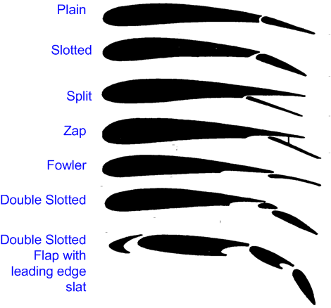
Flap Variations
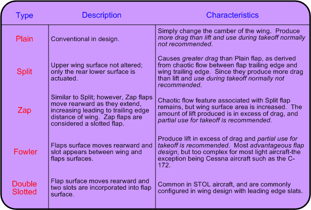
There are six types of flaps commonly used:
Stability
Aeroplane movement is based on three axes: the vertical (normal) axis, the lateral axis, and the longitudinal axis; all three axes pass through the aircraft C of G; stability is defined as the tendency of an aircraft to return to, stay at, or move farther from its original attitude after it has been displaced. There is positive, neutral, and negative stability, and stability is separated into static and dynamic categories
Longitudinal
Movement around the longitudinal axis is roll, which produces bank, and is produced by the ailerons; longitudinal stability (of the axis) is provided by a nose-heavy design and a negative-lift tail.
Lateral
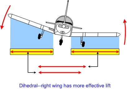
Movement around the lateral axis is pitch, and is produced by the elevator; lateral stability (of the axis) is provided by dihedral, which lowers C of G relative to the lifting surfaces (wing tips are positioned higher than the wing roots); in short, the downward moving wing has greater lift than an upward moving wing.
Directional
Movement around the vertical (normal) axis is yaw, and is “controlled” by the rudder; adverse yaw takes place during rolling movement because of aileron drag, and is controlled by rudder; stability of the vertical axis is referred to as directional stability, and is produced by the vertical stabilizer and sweptback (sweepback) wing design.
Dutch Roll
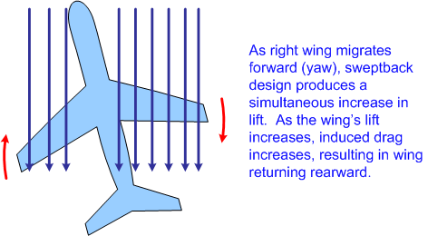
The term Dutch roll refers to a tendency for an aircraft to roll whenever there is yaw. Swept wing aircraft are particularly susceptible, and many are equipped with yaw damper, which is an automatic device that senses yaw and counters it with corrective control inputs before the Dutch roll oscillations can develop. Gregory N. Brown and Mark J. Holt describe the phenomena as follows:
Dutch roll is caused by an aircraft’s tendency to sideslip slightly when the aircraft yaws. One wing yawing forward in this situation changes the effective span between left and right wings. The wing yawed forward momentarily creates more lift than the one of the other side. The result is that the forward wing rises and starts a rolling movement. The problem is aggravated by the fact that the forward wing, due to its increased lift, also has more drag, pulling that wing back once again and starting an oscillation in the other direction.5
Forces during Takeoff
There are many forces that produce left yaw tendencies in most aircraft and must be controlled by rudder,
Torque—caused by prop and engine: movement in one direction causes movement in another.
Precession—a gyroscopic force whereby pressure exerted on a spinning mass will cause a reaction 90° along the direction of rotation.
Asymmetric thrust or P-factor—during high-pitch attitudes (climbs), the downward moving side of the prop disk produces greater lift than the upward moving side. Viewed from the pilot seat, the right side of the prop disc is the down-going side and therefore produces greater thrust than the up-going left side (in most conventional engines).
Slipstream—propeller slipstream spirals around the fuselage and strikes the vertical stabilizer on the port side.
Critical Engine
The effect of asymmetric thrust in multi-engine aeroplanes is to create what is referred to the critical engine. The critical engine is defined as the engine that, should a failure occur, will most adversely affect aircraft performance and control.
On a twin-engine aircraft when both propellers turn clockwise (as viewed from the rear of the aircraft), the failure of the left engine will have the more adverse effect because the remaining thrust from the right engine, owing to asymmetric thrust, would be further from the longitudinal axis than would be the case if the right engine failed and only the left were producing thrust.
Note that some twin-engine aircraft do not have a critical engine as the right engine has a counter-rotating propeller.
High-speed Flight
Compressibility
High-speed flight is flight near, but below the speed of sound. Below high-speed—what is regarded as slow-speed flight—the movement of air around an aircraft during flight does not involve compression of the airflow—what is referred to as compressibility. Instead, the behaviour of slow-speed airflow entails the rules of aerodynamics discussed thus far—the flow of air is like the flow of water around rocks in a stream, where the flow accelerates or slows, based on size and surface features of obstructions to the flow of water. In contrast, high-speed flight is different. Because of the speed of the airframe and wings, etc., the air cannot move out of the way; instead of flowing around the wing, for example, the air cannot get out of the way fast enough, resulting in a compression of the air particles. Compressibility introduces radical changes in aerodynamic principles of high-speed flight.
As the aircraft moves through the air, a pressure wave is propagated ahead of the aircraft,6 which, as Linda D. Pendleton describes, effectively warns the air molecules that lie in the path of the aircraft that the wings, fuselage, etc., are coming, enabling them to organize and smoothly streamline around the structure of the aircraft. As the aircraft speed increases and approaches the speed of the propagated pressure wave, less and less warning is provided and smooth orderly flow is lost. Linda D. Pendleton describes the situation as follows:
As speed increases, the aircraft comes closer and closer to the air particles before they are “warned” by the advancing pressure wave and can change direction. The greater the aircraft speed, the fewer air particles will be able to move out of its path. As a consequence, the air particles begin to pile up in front of the aircraft, and the air density increases.7
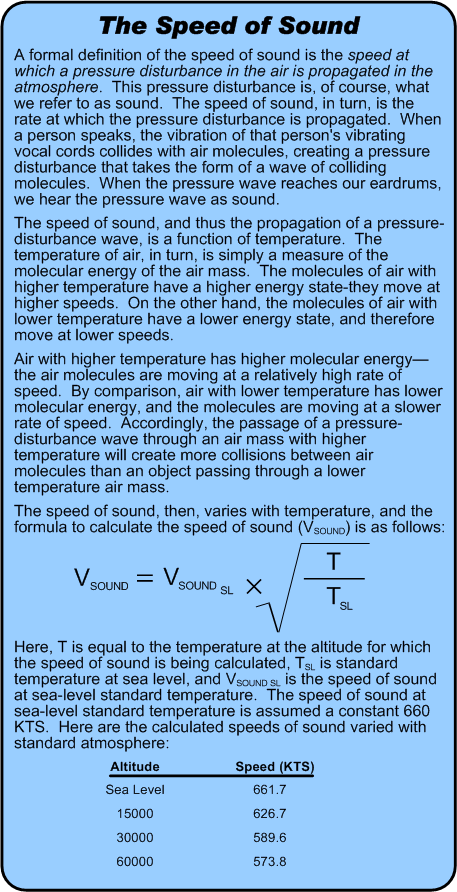
The pressure wave, then, conditions the air particles, allowing them to get out of the way of the airframe; as the aircraft approaches high-speed flight, the pressure wave can no longer radiate in front of the aircraft structure, and the air particles begin to compress—i.e, the phenomenon of compressibility develops. The speed of the pressure wave is, of course, the speed of sound, and compressibility occurs when the aircraft itself approaches the speed of sound.
The concept of compressibility goes a long way to explain the thin design of leading edges of high-speed wings and fuselage designs, and aeronautical engineers attempt to reduce as much as possible the effects of compressibility. Essentially, compressibility inhibits laminar flow, and instead of the air particles accelerating smoothly, the speed of airflow decreases dramatically.
Transonic Flight
The speed of air flow over the upper camber of a wing varies, and it follows, therefore, that portions of the air flowing over the wing will attain the speed of sound—Mach 1.0 (M 1.0)—first, while other portions of airflow remain subsonic. As indicated in the depiction to the right, supersonic speed first develops at the area of maximum airfoil thickness. While this portion has attained M 1.0, remaining portions of the wing, as well as the airframe, remain subsonic. When this happens, an aircraft is said to have reached its critical Mach number (MCRIT), and this marks the beginning of the transonic speed range. Pendleton writes as follows:
Critical Mach number . . is an aircraft limitation to be heeded. If the aircraft is flown at speeds in excess of its critical Mach number, numerous unsettling and potentially disastrous events occur. . . Boundary layer separation on the control surfaces might cause the surfaces to rapidly oscillate, which is called buzz. This can cause metal fatigue problems in both the control surfaces and the hinge fittings joining the control surface to the wing . . Shock-induced separation of the airflow over the control surfaces causes them to be in an area of turbulent, nonstreamlined air that causes a loss of effectiveness. When there is a shock wave in front of the control surface, deflection of the surface cannot influence the airflow in front of the shock wave . . The wings might begin to twist due to compressibility effects. The airfoil shape over the length of the wing is seldom constant, and the differing onset of formation of shock waves and movements of centers of pressure cause this effect. This effect is unnerving at the least. . . Severe buffeting will almost surely be the next compressibility effect that is sure to show up. The extremely turbulent airflow separated from the wings begins to bang against the tail surfaces in a manner that is violent and irregular and disturbs the flow patterns around these surfaces causing them to buffet . . This buffeting, if allowed to continue, has been known to cause separation of the tail from the aircraft . . . If all this has not caused the pilot to slow down and escape compressibility effect by now, a more violent effect is about to occur. Loss of longitudinal stability will cause the aircraft to “tuck under” . . The important point is that the first signs of compressibility effects call for immediate pilot action. The airspeed must be reduced, and the nose must be eased up. The power reduction has to be fast, for when the tuck starts and the aircraft starts into a dive, the situation is going to get rapidly worse. The increased speed will cause the separation of the airflow to become more pronounced, and the severity of the buffet will become greater. The greater the turbulence over the tail, the greater will be the elevator angle and the stick force required to pull out of the dive. Some have not been successful in this manoeuvre, and some have lost the tail of the aircraft before they had time to begin recovery.8
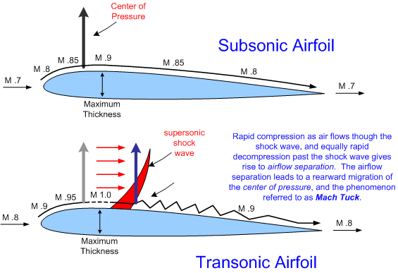
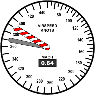
Generally speaking, corporate jets and airline jets are designed to cruise at speeds between M .7 and M .9. Exceeding these speed will produce Mach tuck and the other rather unpleasant flight characteristic described by Pendleton. So the question arises as to how the pilot is advised as to the proximity of the aircraft’s speed relative to MCRIT. Effective communication is complicated by variations in Mach 1.0, based on altitude and temperature. While slow-speed aircraft are speed-limited by Vne, high-speed aircraft are speed limited by the expression MMO—the maximum operating speed relative to the speed of sound. MMO is displayed automatically on the airspeed indicators of high speed by what is referred to as the barber pole—a self-adjusting needle that predicts the MMO based on ambient temperature and pressure altitude. An aural over-speed warning device is also wired to the system—referred to as a clacker.
References
1 Of course, we know these vortices as wake turbulence, which is greatest with large, slow speed, clean configuration aircraft—all features of flight in which the angle of attack is at its greatest.
2 From the Ground Up, P. 33 (Theory of Flight, Turns)
3 Also referred to as topsails.
4 Gregory N. Brown and Mark J. Hold, The Turbine Pilot’s Flight Manual (1995, Ames: Iowa State University Press), p. 66.
5 The Turbine Pilot’s Flight Manual (1995, Ames, Iowa State University Press), P. 150.
6 This pressure wave, incidentally, is what we refer to as sound—sound is simply a pressure wave (noise) that is detected by our eardrums.
7 Flying Jets (Toronto, McGraw-Hill, 1996), P. 42.
8 Flying Jets (Toronto, McGraw-Hill, 1996), Pp. 43-48
.jpg)
