.jpg)


FLIGHT OPERATIONS
- FLIGHT OPERATIONS
- Flight Information Services
- Pressure and Density Altitude
- Weight and Balance
- Landing Considerations
- Wake Turbulence
- Hydroplaning
- Canadian Runway Friction Index (CRFI)
- NOTAMs
- Mid-air Collisions
- Bird Strikes
- Flight over Water
- Winter Flight Operations
- Marshalling Signals
- Mountain Flying
- Aviation Fuel Handling
- Emergency Locator Transmitter
- Medical Factors
- Performance Graphs
Flight Information Services
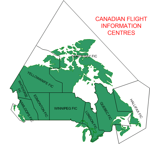
Pre-flight information is obtained from a NavCanada distribution network composed of regional Flight Information Centres (FICs). There are nine FICs in Canada—based in Kamloops, Edmonton, Winnipeg, London, Quebec City, Halifax, North Bay, Yellowknife, and Whitehorse—and the regional distribution of these centres is indicated in the depiction that appears to the right. Pilots can also obtain flight information from a Flight Service Station (FSS) located at specified airports, but FSS are primarily oriented to providing information services to pilots departing and arriving at the specific airport where they are located.
The primary functions of the FIC is to provide pilots with access to emergency services, aviation weather information, flight planning administration, en route flight information, and airport advisory services. The nearest FIC can be contacted using the toll-free number 1-866-WX BRIEF.
When a pilot planning a flight communicates with the FIC, the pilot should begin by describing the planned routing, time, and altitude, and then request “a briefing”. In response, the Flight Service Specialist will convey all pertinent information pertaining to the flight, including weather, AIRMETs, NOTAMs, and PIREPs.1 All of this information is published on NavCanada’s website—www.flightplanning.navcanada.ca—and where possible, pilots should review this data prior to contacting the FIC, and advise the Flight Service Specialists accordingly. NavCanada has also established internet access to flight data through a series of Pilot Information Kiosks, currently situated at 80 airports across Canada. Kiosk locations are published on NavCanada’s internet site, and are also specified in the Canada Flight Supplement.
En route Communication
During a flight, pilots exchange updated information with the FICs via a network of Remote Communication Outlets (RCOs), as well as radio communication equipment co-located at airports (see P. 189). Currently, the frequency 126.7 MHz is the frequency monitored by both pilots and FSS/FIC personnel for the purpose of in-flight communication (see P. 189), but owing to frequency congestion, frequency 126.7 MHz will be phased out by 2010, and replaced by the frequencies 123.275 MHz, 123.375 MHz, 123.475 MHz, and 123.55 MHz. These frequencies shall be referred to as Flight Information Services En route (FISE). Remember, however, that all ATC and ATS units, including FSSs and FICs continuously monitor 121.5 MHz for the purpose of emergency communications.
When contacting the FIC via radio for the purpose of obtaining in-flight information, pilots must transmit the following information: aircraft identification, the name of the location of the RCO, followed by the expression “R-C-O” in non-phonetic format:
|
Pilot: |
Pacific Radio, this is Cherokee Golf, Alpha, Bravo, Charlie on the Lytton R-C-O. |
To avoid confusion in call signs between Kamloops FSS, which administers information at the Kamloops Airport, and Kamloops FIC, which administers information for the Kamloops Flight Information Centre, the Kamloops FIC is referred to as Pacific Radio for the purpose of radio communication (as indicated in the above example).
The frequencies 122.75 MHz and 123.45 MHz are reserved for pilot-to-pilot (air-to-air) communications.
Pressure and Density Altitude
There are many occasions in which a pilot has to predict the performance of an aircraft—e.g., in planning a takeoff, in planning a climb over mountainous terrain, in predicting rates of fuel consumption, and aircraft performance with respect to speed.
Generally, aircraft performance—in terms of lift generated by the wing, and thrust generated by the engine—decreases with an increase in ambient temperature and a decrease in ambient air pressure.
The concept of pressure altitude allows us to take into consideration any variation in the ambient pressure. We know that standard pressure—the pressure most likely to be encountered—is 29.92”Hg (inches of mercury) at sea level. We also know that the pressure of the air normally decreases 1”Hg with an 1000’ increase in altitude. Therefore, if we are at an airport with sea level elevation, and the current altimeter setting is 29.92”Hg, we can predict that the aircraft during the takeoff, for example, will perform as if it is doing the same takeoff at an airport with an elevation of 1000’, and performance will be degraded accordingly. Conversely, if the altimeter setting were 30.92”Hg—i.e., the pressure of the air is higher than normal or standard—the takeoff performance of the aircraft would be enhanced—as if the takeoff were conducted at an airport situated 1000’ under sea level where thick dense air (not water!) would provide better conditions for lift from the wing surfaces and thrust from the propeller and engine.
Calculation of pressure is done by calculating the difference between the current altimeter setting and the standard altimeter setting. This difference is then converted into feet, based on the given that 1”Hg = 1000’—this is referred to as the Standard Pressure Lapse Rate. Accordingly, if the current altimeter setting is 30.12”Hg., we would calculate as follows: 30.12 – 29.92 = .2. Using the standard lapse rate, .2 is converted into 200’. What do we do with this 200’? The answer is that if we want to determine the pressure altitude for an airport, we must add or subtract the 200’ relative to the airport’s elevation. If we want to determine the pressure altitude of an intended altitude that we want to cruise at, we must add or subtract the 200’ relative to the planned cruising altitude. The question of adding or subtracting the “correction value” is determined by whether the current air pressure is higher or lower than standard. Since pressure decreases with altitude, and the current altimeter setting is higher than standard, we should subtract the 200’. Thus, if the airport elevation were 3427’, we can say that the airport’s pressure altitude is 3227’ for the purpose of determining takeoff performance, and if the planned cruising altitude were 6500’ we know that when we level off with 6500’ indicated on the altimeter, the aircraft will burn fuel and produce an indicated airspeed as if it had levelled off at 6300’.
While pressure altitude provides a correction for pressure, it does not take into consideration the ambient temperature of the air—a factor that, on a hot day when performance of the aircraft is degraded, is far more critical.
In factoring in the influence of temperature on aircraft performance we shift to the concept of density altitude—that is, the higher the temperature, the higher the density altitude. Here we must use math, and the formula is as follows:
Density Altitude = Pressure Altitude + (100 ´ [actual temperature – standard temperature] )
Okay, now you are asking “what the heck is ‘standard temperature’?” The standard temperature at sea level is 15° C, and the standard temperature lapse rate is 2°/1000’ (actually 1.98° per 1000’, but the .02 that is missing never hurt anyone). (The origin of the standard temperature lapse rate is discussed on Page 213) What then is the standard temperature for an airport with an elevation of 2000’? The answer is 11° C as, we know, temperature will decrease 2° C for every 1000’ increase in altitude (15-4=11).
So we can see by the formula that density altitude will equal pressure altitude when the actual temperature is in fact the standard temperature for a given elevation or cruising altitude. What is the standard temperature for a given airport with an elevation of 4000’? The answer is this: 4 ´ 2 = 8 and 15 – 8 = 7, or 7° C.
Now we can go into action: What is the density altitude of an airport with an elevation of 4,500’ when the altimeter setting is 28.92”Hg., and the temperature is 28° C.?
Density Altitude = Pressure Altitude + (100 ´ [28 – (15 - 9)])
Density Altitude = 5,500’ + (100 ´ [28 – 6)])
Density Altitude = 5,500’ + 2,200
Density Altitude = 7,700’
You can see how, with only a moderate increase in temperature, the performance of an aircraft can be extremely degraded—and a white-knuckle takeoff is truly something to avoid! For this reason, Pilot Operating Handbooks publish various tables that enable a pilot to calculate performance characteristics at varying temperatures and altitudes.
Instead of memorizing the above formula, consider the good news—density altitude can be readily calculated by spinning the wheel on the E6B, and the temperature and pressure factors are normally built into the performance charts published by an aircraft manufacturer’s Pilot Operating Handbook. The graph that appears to the right is similar to that which appears on p. 9-1 of the Cherokee manual.
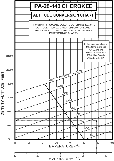
This graph is entered on the bottom with temperature (either in °F or °C—your E6B, by the way, is equipped with a conversion scale). In the example shown on the graph, the temperature is 32° C, and the pressure altitude is 3500’—figures that are common for summer departures from airports such as Calgary International Airport. A line is referenced straight up from the temperature scale to intercept the pressure altitude lines that run at an angle. From this intercept point, a horizontal reference line is made directly to the density altitude scale which lies on the left side of the graph. The density altitude for the departure is approximately 5500’.
Weight and Balance
There are various terms associated with weight and balance:
|
Standard Weight Empty (Standard Empty Weight) |
The weight (referred to as Standard Weight Empty or Standard Empty Weight) of the airframe and engines with standard equipment, including unusable fuel and oil. |
|---|---|
|
Usable Fuel |
Aircraft fuel available for flight. |
|
Unusable Fuel |
Aircraft fuel remaining in the tanks that is unreliable and cannot be used. |
|
Basic Empty Weight |
The weight of the aircraft with the current equipment options (instruments, radios, interior features), excluding passengers, cargo and usable fuel. Basic empty weight sometimes includes full oil weight, and the pilot must examine the aircraft weight and balance list to determine if oil weight is included. |
|
Operational Weight Empty |
The Basic Empty Weight of the aircraft and weight of the flight crew, excluding payload and usable fuel. |
|
Maximum Gross Weight |
The maximum permissible weight of the aircraft. |
|
Useful (Disposable) Load |
Gross takeoff weight, less basic empty weight. |
|
Payload |
The weight load available for passengers and cargo (revenue items) after the deduction of the weight of the flight crew and usable fuel. |
|
Maximum Weight—Zero Fuel2 |
The maximum weight of the aircraft, including useful load, but excluding usable fuel. Where such weight is published for an aircraft, it is because the need for structural integrity of the wings whereby the weight of fuel is needed to offset the load imposed by lift. |
|
Operational Gross Weight |
Weight of the aircraft loaded for takeoff (Basic Empty Weight plus Payload). |
|
Maximum Takeoff Weight |
The maximum permissible weight to conduct a takeoff. |
|
Maximum Landing Weight |
The maximum permissible weight to conduct a landing. |
|
Maximum Ramp Weight |
The maximum permissible weight of an aircraft for ground manoeuvring. |
2 Also referred to as the Maximum Zero Fuel Weight or the Maximum Allowable Zero Fuel Weight. Don’t get this confused with zero fuel weight, which is normally calculated pre-flight for determining the maximum fuel that can be put on board after the Payload.
Weight and Balance Requirements
Before each flight, the pilot must ensure that the aircraft conforms to the weight and balance limitations established by the manufacturer for every phase of flight—this includes the takeoff and projected landing weight and balance, but it also includes zero-fuel weight and balance should the pilot have to extend its intended flight time and aircraft fuel requirements owing to unforeseen circumstances such as an unplanned diversion.
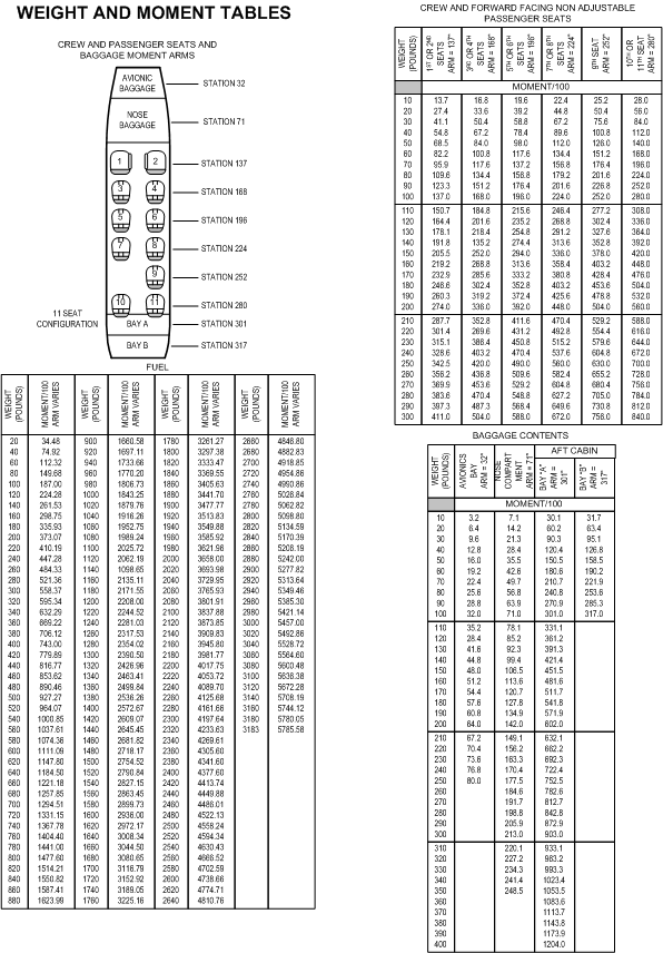
The C of G is the central balance of the aircraft—the point at which it could be suspended and remain balanced— and is calculated using the load positions or stations prescribed in the Pilot Operating Handbook and the actual load anticipated for an intended flight.
Aeroplane manufacturers publish weight and balance limits, including the Standard Empty Weight in the aircraft’s Pilot Operating Handbook. In addition, each aircraft has a unique Aircraft Weight and Balance Report that reflects all equipment unique to the aircraft. The Aircraft Weight and Balance Report must reflect the current Equipment List for the aircraft, and there must be documentation of the aircraft’s current Basic Empty Weight and C of G data. The Aircraft Weight and Balance Report may be based on historic calculations as equipment is added and/or removed—in which case the documents will include a series of superseded weight and balance reports—or it may be based on the actual weighing of the aircraft. In all cases, the weight and balance status of the aircraft must be readily discernible.
In the Weight and Balance section of the Pilot Operating Handbook, data provides an arm for each station, which is the distance in inches from a predetermined balance datum line (the datum line is simply a reference line that allows measurement of the longitudinal position of the stations). Typically, station arms are provided for the flight crew and/or front passengers, the various passenger seat positions, cargo compartments, and fuel tanks. The weight and balance is calculated by using the station arm and anticipated weight at each station, as well as the aircraft BEW and its corresponding C of G as derived from the Aircraft Weight and Balance Report.
Weight and Balance Procedure
For each station item, the weight is multiplied by the arm to establish (for each position) a moment. To determine the aircraft C of G, the total moment (all station moments added together, including the BEW moment) is divided by the total weight. The sum, in inches, provides the C of G for the aircraft and is compared with the aircraft C of G “envelope” found in the Pilot Operating Handbook to determine if it is within limits.
A computation table, such as appears below, helps simplify the calculations. In this example, the total weight (1995 lbs.) is added up to ensure it is within the permissible limit; then the total moment (175,615) is divided by the total weight to provide the centre of gravity (88.0 inches); finally, this C of G number, along with the total takeoff weight of the aircraft, is checked against graphs found in the Pilot Operating Handbook to determine if the aircraft is within permissible limits.
|
Item |
Weight (pounds) |
Arm (inches) |
Moment |
|
|---|---|---|---|---|
|
Basic Empty Weight |
1380 |
85.0 |
117,3003 |
|
|
Pilot and Front Passengers |
320 |
85.5 |
27,360 |
|
|
Rear Passengers |
90 |
117 |
10,530 |
|
|
Fuel (usable) |
180 |
95 |
17,100 |
|
|
Baggage Area #1 |
25 |
133 |
3,325 |
|
|
Totals |
1995 |
|
175,615 |
|
|
C of G: |
175,615 1995 |
= 88.0 |
||
3 This calculation of the moment is based on weight times arm—1380 × 85.0 = 117,300. The unit of the moment is commonly referred to as pound-inches—e.g., 117,300 pound-inches.
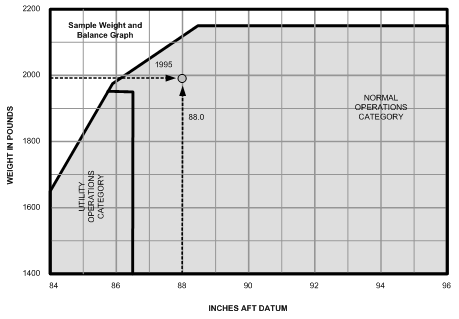
These graphs commonly depict the maximum aft C of G and the maximum forward C of G in relation to various takeoff weights. In the sample graph that appears above, the maximum forward limit is 84 inches aft datum, and the maximum rearward limit is 96 inches. To conduct a takeoff beyond these limits would be deadly. Note also that the maximum takeoff weight—for this aircraft, 2150 lbs.—could only be used when the C of G is between 88.5 inches and 96 inches; as the weight is reduced, the C of G must migrate forward of 88.5 to remain within the graph limits. Finally, note how this graph sets the legal limits for utility category manoeuvres, such as spins, or steep turns in excess of 45° bank (see discussions on P. 41).
While the format of the above weight and balance graphic is typical of many aircraft such as the Piper Cherokee, there is a second format commonly used. In the Pilot Operating Handbook of Cessna aircraft, for example, the determination of the aircraft’s balance point does not include the calculation of the C of G directly; instead the pilot determines the balance point by calculating the total moment of the aircraft—i.e., simply adding all the moments together—and then comparing this number with the aircraft’s total weight.
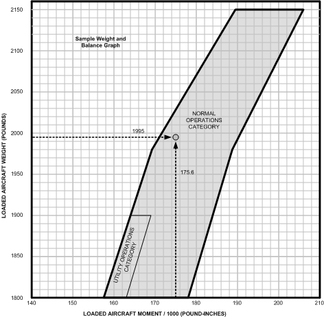
In the above example we have used, the total moment was of course 175,615, a unit referred to as pound-inches. Since this figure is commonly large and cumbersome, the number is typically divided by 1000; so 175,615 lb-in. would become 175.615 lb-in/1000. (The unit names have the appearance of rocket science, but in fact it is all real simple stuff.) It is the 175.6 figure, along with the total weight of the aircraft (1995 lbs.), which is checked against graphs in the aircraft’s Pilot Operating Handbook. As shown in the graph that appears below, the information presented is more or less identical to that which appears in the previous weight and balance graph.
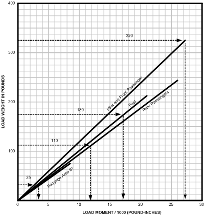
To determine the pound-inches/1000 a second specialized graph is used which makes this format of weight and balance quite easy to calculate. This second graph appears above, and you can see that each station—pilot and front passenger, Rear passenger, fuel, etc.—has its own reference line.
The weight for each station establishes a point on the reference line, and the station moment (lb-in/1000) is determined by extension of a downward vertical line. These can then be entered on a table, as shown below.
|
Item |
Moment (lb.-inches/1000) |
|---|---|
|
Basic Empty Weight |
175.6 |
|
Pilot and Front Passengers |
27.3 |
|
Rear Passengers |
10.5 |
|
Fuel (usable) |
17.1 |
|
Baggage Area #1 |
3.3 |
|
Totals |
175.8 |
There may be some confusion over the fact that 175.8 value appears in the above table instead of the 175.6 figure that is plugged into the graph above; the reason for this is that the last two digits are dropped when using the load-weight graph to the right—the difference is inconsequential.
Actual passenger weights must be used in calculating weight and balance, but if these are not available, the following average passenger weights (published in the Aeronautical Information Manual) can be used:
|
Type of Passenger |
Summer Weight |
Winter Weight |
|||
|---|---|---|---|---|---|
|
MALES (12 years and up) |
200 lbs. (90.7 kg.) |
206 lbs. (93.4 kg.) |
|||
|
FEMALES (12 years and up) |
165 lbs. (74.8 kg.) |
171 lbs. (77.5 kg.) |
|||
|
CHILDREN (2 – 11 years) |
75 lbs. (34.0 kg.) |
75 lbs. (34.0 kg.) |
|||
|
INFANTS (less than 2 years) |
30 lbs. (13.6 kg.) |
30 lbs. (13.6 kg.) |
NOTE:
- On any flight involving a number of passengers whose weights, including carry-on baggage, will exceed the average weights listed above, the actual weights of such passengers are to be used.
- The weight of infants must be added separately when the infant’s weight exceeds 10% of the adult responsible.
- Where carry-on baggage is not involved or permitted, the weights for males and females may be reduced by 13 lbs (5.9 kg.).
|
Item |
Weight (pounds) |
Arm (inches) |
Moment |
|---|---|---|---|
|
Basic Empty Weight |
1380 |
85.0 |
117,3004 |
|
Pilot and Front Passengers |
320 |
85.5 |
27,360 |
|
Rear Passengers |
90 |
117 |
10,530 |
|
Oil |
22 |
-15 |
-333 |
|
Fuel |
180 |
95 |
17,100 |
|
Baggage Area #1 |
25 |
133 |
3,325 |
|
Totals |
2017 |
|
174,949 |
|
C of G: |
174,949 2017 |
= 86.7 |
Note that the Aircraft Weight and Balance Report for some aircraft includes oil, while others do not; where oil is not included, the oil station (including weight, arm, and moment) must be added to the pre-flight calculations. This can only be determined by examining the actual report, including the equipment/weight list included in the Report. Oil weights are published in the Canada Flight Supplement. On occasion, oil is presented as a negative value in the weight and balance calculations (this appears in the table to the right), and this is because the location of oil is sometimes behind the datum line. Not to worry, here, as the negative moment value for oil (-333 lb.-inches in the case above) is simply subtracted in reckoning the total moment value. Negative values appear typically when the reference datum line is configured at the firewall (separating the engine and cabin compartments), but it is more common for designers to place the reference datum line at or near the spinner.
In calculating average fuel and oil weights, it is generally assumed that aviation fuel weighs on average 6 lbs. per U.S. Gallon and oil weighs 1.95 lbs. per litre.5 In fact, however, the weight of these fluids varies with temperature, and for this purpose tables—as is published in the RAC (3.5.2) of the AIM are used. Here is as example:
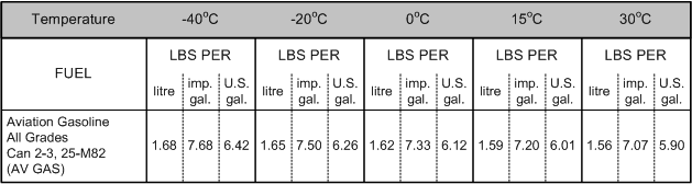
Fuel and oil weights are also published in the Canada Flight Supplement.
Note that the Aircraft Weight and Balance Report for some aircraft includes oil, while others do not; where oil is not included, the oil station (including weight, arm, and moment) must be added to the pre-flight calculations. This can only be determined by examining the actual report, including the equipment/weight list included in the Report.
Cessna 441 Weight and Balance
The Cessna 441 is a useful example of administering weight and balance on more advanced aircraft, and as is immediately apparent from the graph and table that follow, the same calculation methods are used here as are applied to small aircraft:
So you can see that each one of the applicable stations is covered for this aircraft and the calculation would simply revolve around producing a list of Moment/100 values for each weight item, to produce a total Moment/100 value.
A sample weight and balance form is produced by the manufacturer as follows:
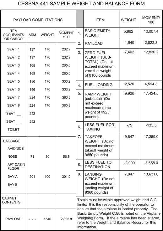
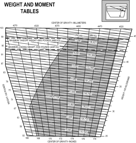
The Payload Computations are completed on the left of the form, and this includes the crew, passengers, and some baggage. The payload value (1583 lbs. and 2822.8 Moment/100) is then entered on the right of the form with the aircraft’s basic empty weight (5862 lbs. and 10,007.4 Moment/100) to give the aircraft’s zero fuel weight (Item 3.)—note here as well the maximum zero fuel weight limit on the C441 of 8100 lbs. With the fuel added (Item 4.), the ramp weight is determined (Item 5.), etc. Note the maximum takeoff weight (Item 7.) and the maximum landing weight (Item 9.).
The takeoff, landing, and zero-fuel weight values are then plotted on the aircraft’s weight and balance envelope as follows:
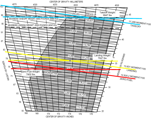
This graph is entered from the left side using the weight of the aircraft (divided by 100 lbs.) and your pencil will move to the right, parallel to the horizontal weight lines, until you intercept the appropriate Moment/100 (IN-LBS) line—these lines at a slight angle from lower right to upper left). From this intersect your pencil will move downward to the bottom of the graph to read the Centre of Gravity value, and of course this movement should be parallel to the Centre of Gravity lines. Note that the Moment/100 scale is inserted within the graph, and be sure you don’t get confused by Center of Gravity Millimetres and Weight-100 Kilograms scales, which are for conversion purposes only.
Weight, Balance and Performance
The heavier the aircraft, the greater the lift required from the wing throughout the speed range. Consider, for example, two identical aircraft, one lightly loaded and the second heavily loaded. If both are flying at the same indicated airspeed, it is clear that the heavier aircraft must have a higher angle of attack (to produce the extra lift) than the lighter aircraft. For a given speed, including speed just above the stall, it must be that the angle of attack of the heavier aircraft is closer to the critical stall angle of attack than the light aircraft—it follows, therefore, that the lighter an aircraft, the slower its stall speed.
The same argument as above can be applied to fuel economy. That is, the aircraft with a lower angle of attack for a given speed must have less induced drag and therefore less thrust (fuel burn) will be required.
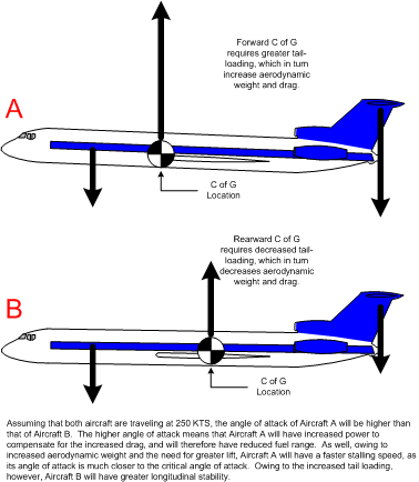
The location of the C of G with respect to whether it is forward or rearward also affects aircraft performance. While an aircraft takes off with a specific ramp weight, once it leaves the ground the effective negative lift of the horizontal stabilizer has the effect of increasing the aircraft’s aerodynamic weight. If a C of G is located forward, the negative lift of the tail will have to be increased to balance the forward weight, and as the negative lift is increased, the aerodynamic weight, overall, is increased. Using the same reasoning as applied above with respect to weight in general, an aircraft with a forward C of G will have a higher stall speed than the aircraft with a rearward C of G. A forward C of G loading, however, has a positive effect with respect to stability—an aircraft with heavy tail loading will be more stable in recovering from a pitch-down attitude as the associated acceleration will activate a greater amount of horizontal stabilizer weight, thereby making it easier to raise the nose. Also, at the point of stall, a forward C of G will make recovery easier (the pilot has more pitch authority on the control column than is the case with a rearward C of G).
These features, of course, are related to loading variations within limits. An aircraft loaded outside limits is simply dangerous. Always ensure weight and balance is within limits—if it is not and you have an accident, your insurance will not cover property or personal liability.
1 AIRMETs pertain to unexpected changes in the weather conditions that were previously not published in the aviation forecasts; PIREPS are pilot reports pertaining to weather conditions observed by a pilot during flight, and communicated to FSS/FIC personnel on the ground. These are discussed on P. 267.
4 This calculation of the moment is based on weight times arm—1380 × 85.0 = 117,300. The unit of the moment is commonly referred to as pound-inches—e.g., 117,300 pound-inches.
5 One U.S. Gallon contains 3.79 litres.
Shifting Weight
The calculation to shift loads may be necessary in cases where the aircraft weight is within limits, but the C of G is outside permissible limits. To affect a change in the C of G location, the question therefore arises as to how much weight must be moved, and how far must that weight be moved relative to a datum.
The formula to conduct this calculation is as follows:
|
w W |
= |
d D |
Where,
|
w |
= |
weight to be moved |
|---|---|---|
|
W |
= |
weight of the aircraft |
|
d |
= |
distance C of G must move |
|
D |
= |
distance between arms of the stations used in the move |
The formula is generally applied in two ways. In the first instance the weight of object is unknown, and the pilot is simply faced with moving weight between two specific cargo areas on board. In the second instance, the weight of the object is known, and the pilot must determine how far the weight must be shifted to bring the C of G into limits.
Problem #1: A pilot is attempting to correct a weight and balance problem where the C of G is too far aft. The maximum aft limit of the C of G for the aircraft is 94.6” aft datum, but the calculated C of G indicates 96.2” aft datum. As currently loaded, a number of moveable cargo items are located in the Aft Baggage compartment with a published distance aft datum of 178.7.” Some of these cargo items can be moved to the Forward Baggage compartment which has a published distance aft datum of 22.5.” If the gross weight of the aircraft is 4334 lbs., what amount of weight must be moved forward?
| w
W |
= |
d D |
|
w 4334 |
= |
(96.2 - 94.6) (178.7 - 22.5) |
|
w 4334 |
= |
1.6 156.2 |
|
w |
= |
1.6 x 433.4 156.2 |
||||
|
w |
= |
6934.4 156.2 |
||||
w=44.4
A cargo item weighing 44.4 lbs. must therefore be moved from the Aft Baggage compartment to the Forward Baggage compartment.
Problem #2: Using the same aircraft, a pilot has a 232 lbs. cargo item in the Aft Baggage compartment, but when the weight and balance calculation is done, the C of G is located 4.3” aft of the maximum aft limit. If the gross weight of the aircraft is 3980 lbs., how far forward must the cargo item be moved?
|
w W |
= |
d D |
|||||
|
232 3980 |
= |
43 D |
|
D 43 |
= |
3980 232 |
|
D |
= |
3980x43 232 |
||||
|
D |
= |
17114 232 |
||||
|
D |
= |
73.76 |
|
The 232 lb. cargo item must therefore be moved forward 73.76” from its current location.
Mean Aerodynamic Chord
The Mean Aerodynamic Chord (MAC) is simply a concept that provides a means of expressing the C of G location relative to a percentage of the distance between the maximum forward and rearward distance along the aircraft wing chord. In the case of aircraft with a symmetrical chord line from wing root to wing tip, the MAC would be the distance from the leading edge to the training edge—in the case of aircraft with swept wings, the MAC is calculated as the mean average chord as a means of simplification.
.gif)
The illustration above (Wikipedia) shows the MAC concept. Overall, it is important to remember that the acceptable location of a C of G is usually a small range within the MAC—20% to 35%. Let’s now look at the Seneca’s MAC:
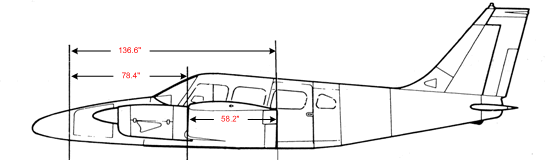
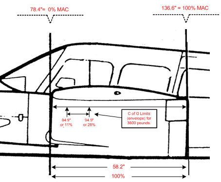
With the concept of MAC applied to the Seneca, above, for example, we can speak of the leading edge chord as located 78.4” aft datum, and the trailing edge chord as located 136.6” aft datum. MAC distance, therefore, is 58.2”—the distance from the leading edge to the trailing edge of chord line.
If we now superimpose onto the MAC the allowable centre of gravity envelope for the Seneca loaded at 3800 pounds—where the maximum forward C of G is 84.9” aft datum and the maximum rearward C of G is 94.6”—we can see that these limits translates to 11% MAC and 28% MAC:
Now let’s examine at the means by which we calculate the C of G as a percentage of MAC (% MAC). In all cases we have to be given the C of G usable envelope as the % MAC, and in the case of the Seneca at 3800 lbs., we know that the acceptable limits 11% and 28%—that is, the C of G calculated as a % MAC must lie between these two percentages. Okay, here is the question: a pilot calculates the Seneca takeoff C of G as 88” aft datum for the weight 3800 lbs. What is this C of G expressed as a % MAC? Here is the formula and its application:
|
% MAC |
= |
(take-off C of G – Leading Edge Aft Datum) × 100 MAC Distance |
|
% MAC |
= |
(88 – 78.4) × 100 58.2 |
|
|
MAC |
= |
9.6 × 100 58.2 |
|
MAC |
= |
16.5% |
Landing Considerations
Approach Speed for Predicted Weight
While the approach speeds published in the Pilot Operating Handbook for light aircraft is based on maximum gross weight only, larger aircraft make adjustments in the approach speed based on landing weight variations. Where only a maximum weight speed is stated, the following formula can be applied to make speed reduction similar to larger aircraft:
This speed calculation is required for the Commercial Pilot Flight Test. Note that the value given by the formula is calibrated airspeed, and this in turn must be translated to indicated airspeed.
Landing Rules of Thumb
As a rule, the airspeed maintained on short final for a landing should be 1.3 times the aircraft’s power-off stalling speed (calibrated) in a landing configuration (Vso)—i.e., full flaps, and gear down (if applicable). The airspeed should only be flown after all manoeuvring for landing is completed—thus, it only applies to short-final phase of landing, beginning at the midpoint of the final approach leg.
Note that this rule does not apply to all aircraft; as the landing speeds in some aircraft may be prescribed in Pilot Operating Handbook without variation.
Note additionally that the 1.3 Vso rule applies to stalling speeds for the actual weight of the aircraft, as per the stalling speeds found in the aircraft’s Pilot Operating Handbook. Without this information, however, weight adjustments to the final approach airspeed can be made: reduce Vso by one-half the percentage to which the aircraft is loaded below the gross weight. For example, if an aircraft has a Vso of 50 KTS, the short final is normally flown at 65 KTS calibrated; if, however, the maximum gross weight is 2100 lbs., and its actual weight is 1800 lbs., its approach speed should be further reduced by approximately 7% (one-half of 14.29%)—instead of 65 KTS, the approach should therefore be flown at 61 KTS (60.45 KTS to be precise).
When landing in gusting conditions, the final approach speed should be increased by one-half the gust velocity.
Crosswind Landing Limitations
Approximately 10% of all light Canadian aircraft accidents are attributed to pilots’ inability to control the aircraft during crosswind landings.
Using a crosswind chart (found in the Canada Flight Supplement), winds anticipated during a landing can be broken down into two portions: the headwind component, and the crosswind component. The crosswind component is used to predict aircraft performance. Students should be readily familiar with the use of these graphs.
As a rule, North American aircraft are designed to withstand a maximum crosswind equal to 20% of the aircraft stall speed; this figure, however, is conservative, as a skilled and proficient pilot is typically able to land with crosswind components equal to 30% of the stall speed.
Students often err with respect to the proper conversion of winds reported in magnetic degrees, and winds reported in true degrees. Just remember that only the winds communicated by a control tower or by ATIS (recorded airport information transmitted on a radio frequency) is in magnetic degrees; all written weather reports regarding winds, including airport terminal forecasts, describe the winds in true degrees, and must therefore be converted to magnetic.
Remember that a runway heading is based on magnetic degrees in the SDA.
Landing Errors
Wheelbarrowing—danger in tricycle gear aeroplanes, caused by pilot placing too much weight on nose gear with forward control pressure; during takeoffs, this occurs when the pilot attempts to excessively hold the aircraft on the ground; during landings, it occurs commonly in combination with full flaps and excessive speed—again excessive attempts are made to hold the aircraft on the ground, and braking power is reduced as the main gear lacks weight. The solution is to abort the landing and go around.
Balloons and Bounces—excessive back pressure during the flare for landing; the aircraft is caught gaining height above the runway at near-stall speeds—if the aircraft is then dropped onto the runway a bounce will be produced. The solution is to go around or, if safe, add power to re-establish the flare.
Porpoising—aircraft is bounced back and forth on the nose and main gear, caused by improper landing attitude and excessive speed. Smoothly regain the correct landing attitude and add power to become airborne again—go around.
Landing Illusions
Rain on the windshield causes a distortion—refraction—that makes terrain appear lower than it actually is; for example, a hilltop ½-mile away may appear 200’ lower than it actually is.
Also, landing on an upslope runway presents a similar illusion—that you are higher than what you actually are. See the summary of landing illusions that appears on P. 182.
Approach Slope Lights
There are two systems of approach slope lighting. Visual Approach Slope Indicator System (VASIS) is the older system, and is gradually being phased out in Canada, while the new system is Precision Approach Path Indicator (PAPI).
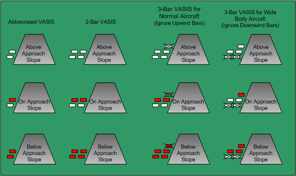
Depicted above are the three varieties of VASIS lighting. Interpretation of the Abbreviated VASIS and the 2-Bar VASIS is relatively straightforward; with respect to the 3-Bar VASIS, however, pilots of non-wide bodied aircraft must remember to ignore the upwind bars.
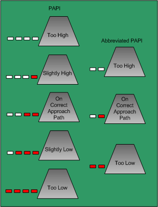
PAPI indications (depicted below) are virtually identical to VASIS lighting, except the slope indications are presented along the horizontal plane.
Wake Turbulence
Wake turbulence is caused by wing tip vortices that are produced by the air pressure differential above and below the wing.
The vortex can produce structural loads as high as 10g. While the up gust/down gust has been estimated at 80 ft. per second (fps), most small aircraft are designed to withstand gusts of 30 fps. (Gusts near thunderstorms can exceed 45 fps.)
The strongest vortices are generated by heavy weight, clean configuration, at slow speeds. Accordingly, the worst is a heavy jet during touchdown and takeoff phases. Note as well that vortex strength varies with aspect radio—an aircraft with high aspect ratio, such as a glider with long, narrow wings, produces minimal induced drag and therefore minimal wing tip vortices, while an aircraft with low aspect ratio (short, wide wings) produces maximum induced drag and maximum wing tip vortices. Finally, remember that helicopters produce dangerously concentrated vortices from the main rotor.
It takes 2 minutes for the strength of vortices to dissipate. As a rule, the smoother the air—non-turbulent air—the slower the dissipation.
During touchdown, the generation of vortices does not stop until the jet’s nose-wheel touches down, while, during takeoff, the vortices are generated as soon as the jet rotates.
Vortices tend to spread out at a speed of 5KT. A 5KT crosswind can therefore hold one of the vortices over the touchdown or takeoff area, or cause them to migrate to adjacent runways.
Wake Turbulence Guidelines
On the Ground
- Before requesting clearance to cross a live runway, wait a few minutes if a large aircraft has just landed or taken-off.
- When holding near a runway, anticipate wake turbulence.
Takeoff
- When cleared to takeoff after a departing large aircraft, plan to become airborne prior to that aircraft’s rotation path, staying above or turning away from its departure path.
- When cleared to take off after a landing large aircraft, plan to become airborne after its nose-down point.
In flight
- Avoid flight below and behind large aircraft.
Landing
- When cleared to land behind a departing large aircraft, plan to touchdown before the rotation point.
- When cleared to land behind a landing large aircraft, remain above its flight path, and plan to touch-down after its nose-down point.
- Plan approach to avoid vortices generated by aircraft operating on parallel or cross runways.
|
Jet Blast Hazard |
||||||||
|
CATEGORY |
IDLE DANGER |
TAKEOFF DANGER |
||||||
|
Heavy |
600’ |
1600’ |
||||||
|
Medium |
450’ |
1200’ |
||||||
|
Light |
200’ |
500’ |
||||||
- It is crucial for safety that all pilots realise that, while ATC is required to issue wake-turbulence cautions, avoidance is solely the pilot’s responsibility.
Jet Blast Hazard
Extreme caution must be used when manoeuvring on the ground at airports where jet operations occur.
As a rule, never taxi behind a jet aircraft unless you can be assured that the engines are not operating; if operating, the distances on the right are to be used for reference.
Two additional things to remember. A taxiing jet or turbo-prop aircraft can produce winds in excess of 60 KTS. Only the pilot has sole responsibility for jet blast avoidance.
Hydroplaning
While a runway with snow or ice provides a somewhat predictable environment with respect to braking action and directional control, this is not the case with a water-covered runway where braking and control are dependent on the rate at which water builds up under the tire.
The speed at which a non-rotating tire hydroplanes—at the point of touchdown during a landing—is lower than the speed at which a rotating tire will begin to hydroplane—takeoff roll.
The prediction of hydroplaning is therefore made with the use of two formulas, both of which factor in tire pressure:
Non-rotating tire:
7.7 × √PSI = speed (KTS) for hydroplaning
Rotating tire:
9 × √PSI = speed (KTS) for hydroplaning
Problem #1: At what speed is there a risk of an aircraft hydroplaning at touchdown if the tire pressure is 50 PSI?
Non-rotating tire: 7.7 × √49 = 54 KTS
The answer, then, is at or above 54 KTS.
Problem #2: At what speed is there a risk of hydroplaning during a takeoff roll?
Rotating tire: 9 × √49 = 63 KTS
The answer is at or above 63 KTS.
Note that hydroplaning a rotating tire—referred to as spin down—is associated with the takeoff roll, which the hydroplaning of a non-rotating tire—referred to as spin up—is associated with touchdown.
Canadian Runway Friction Index (CRFI)
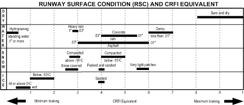
The CRFI index is a measure of predicted braking action and control during landings, based on the presence of natural forms of runway contaminants, such as snow, water, ice, etc. The CRFI index is a scale from 0 (zero) to 1 (one); while CRFI value of 1 predicts maximum braking, a CRFI value of 0 predicts minimum braking. A bare and dry runway will be associated with a CRFI value of between .8 and 1, while, for example, a snow-covered runway would have a CRFI value of between .25 and .30. The approximate values of various contaminants are shown in the upper table.
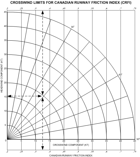
A second CRFI table (also above) is used to predict revised crosswind limits that take into consideration the contaminants and the associated control limits experienced by aircraft. In the example shown on the right, the winds are approximately 40° off the runway at 20 KTS. The crosswind component is about 13 KTS. With a 13 KT crosswind component, the maximum safe CRFI value is about .35. Beyond this maximum crosswind value, the runway condition could result in uncontrollable drifting and yawing during a takeoff or landing. The communication of CRFI values via NOTAM is discussed below.
NOTAMs
A NOTAM is a notice concerning the establishment, condition, or change in any aeronautical facility, service, procedure, or hazard, the timely knowledge of which is essential to flight operations personnel. NOTAMs are typically used to communicate any changes to aeronautical chart and information publications. They are distributed by FSS, and accessible during pre-flight briefings.
The format of NOTAMs is standardized, as is shown to the right with respect to new NOTAMs. The issuing location varies depending on the nature of the NOTAM. If the NOTAM is of general interest to all users, the issuing location will be CYHQ, meaning headquarters. If the NOTAM is of interest to a Flight Information Region (FIR), than the name of the FIR will appear here—for example, Vancouver FIR is CZVR. In the case of NOTAM being applicable to specific locations, the name of the location will be provided—in the case of the example used here, the identifier for Abbotsford Airport is provided.
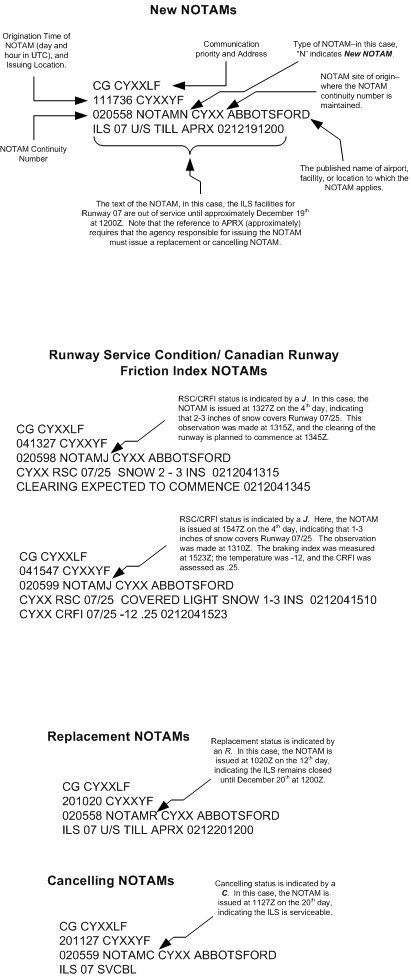
Note that a new NOTAM is indicated by the code letter N appearing behind the word NOTAM. Note also the continuity number that appears at the beginning of the third line—don’t get this confused with any observation or validity times, as it is purely administrative. The date and time format is standardized.
In addition to the new NOTAMs, two other code-letters are used for replacement NOTAMs and cancelling NOTAMs. An important rule regards the appearance of APRX (approximately) in the NOTAM text; when this appears, the issuing agency must provide a cancelling NOTAM to insure there is no confusion.
A final concern relates to the format of NOTAMs that communicate the CRFI and Runway Surface Condition (RSC) reports. RSC/CRFI NOTAMs are issued whenever there is slush or wet snow on a runway, where ever there is loose snow on a runway exceeding ¼-inch, whenever the runway is not cleared to its full width, whenever there is compacted snow, ice or frost on a runway, or whenever the CRFI value is .4 or less.
RSC/CRFI NOTAMs are published with the code-letter J. In the first example depicted to the right, the NOTAM was issued on the 4th day of the month, describing a 2-3 inch covering of snow on the Abbotsford runway. Note the information related to when the clearing of the runway is expected to begin.
In the case of the second depiction, the runway still has a light covering of snow (presumably accumulating since the clearing). This condition was observed at 1310Z. At 1523Z, the runway was tested and rated at a CRFI value of .25, and at the time of the test, the temperature was -12°C.
Mid-air Collisions
A small percentage of these accidents occur head on; nearly all occur in daylight hours in VFR conditions within 5 nautical miles of an airport, usually in the traffic circuit.
A pilot is five times more likely to have a mid-air collision with an aircraft flying in the same direction than with one flying in the opposite direction.
If an approaching aircraft is seen to be fixed, you are on a collision course; if the approaching aircraft has movement, there is no risk of collision. Be sure you do not turn the wrong way.
Never turn, climb, or descend into a blind spot.
During flight, the critical areas to scan are 60° left and right of the flight path, and 10° above and below.
Further Reading: AOPA's Collision Avoidance
Bird Strikes
Since 1912, 200 deaths have resulted from bird strikes on aircraft.
The greatest risk is in flight below 2500’ where 99% of all bird strikes occur.
The faster the aircraft the greater the risk—up to 80-90 KTS, birds have time to get out of the way.
The greatest risk is during March and April, and during September and October, when bird migration occurs.
If you see birds ahead of you attempt to pass over, rather than under, as birds dive downward when threatened.
Anticipate that a bird striking the windscreen will penetrate; use the instrument panel as a shield, anticipate blood and guts, and remember to fly the aircraft.
All bird strikes are to be reported; see the RAC Section of the AIM.
Flight over Water
Common sense is to wear a life jacket whenever your single engine aircraft is beyond gliding distance from shore.
Ditching in water will create panic among already traumatised pilot and passengers as icy-cold water floods what will likely be an inverted cockpit. The dark cabin will be full of debris, loose wires, cables and seatbelts, making the retrieval of life jackets after ditching virtually impossible.
The key is remaining calm. Do not release your seatbelt until you are ready to exit the cabin. Locating the exit handle will be difficult while upside down in murky water, so locate the exit handle while still in your harness. Even with the water pressure equalised on both sides, the door could still be difficult to open, so be prepared to push hard. If unsuccessful, force a window by anchoring yourself firmly, pushing out against the window with both feet. Once the door is open, never let go of the handle until you are out; should you let go, you may not be able to locate it again. Therefore, release your seatbelt while holding the handle and pull yourself out (do not kick as someone may be behind you). If you get stuck, do not panic; back up and turn a little, then try again. Once you are clear of the aircraft, inflate your life jacket (if you inflate your life jacket in the cockpit, this could impede your egress).
Winter Flight Operations
Clean Aircraft Concept
As discussed earlier, the CARs prohibit any takeoff when frost, ice, or snow is adhering to any critical surface of the aircraft—this is referred to as the Clean Aircraft Concept.
Critical surfaces of an aircraft denotes the wings, control surfaces, rotors, propellers, horizontal stabilizers, vertical stabilizers or any other stabilising surface of an aircraft, and in the case of an aircraft with a rear-mounted engine, critical surfaces include the upper surface of the fuselage.
If frost, ice, or snow forms on the leading edge and upper surface of a wing with the thickness and surface roughness similar to medium or coarse sandpaper, wing lift can be reduced by as much as 30% and drag can be increased by as much as 40%.
Aerodynamic Effects of Airborne Icing
Here is a list of the classic aerodynamic effect of ice accumulation on an airframe:
- reduced lift and increased drag and weight;
- increased stall speed and reduced critical angle of attack;
- reduced and degraded thrust;
- control surface restrictions;
- blocked vision owing to windscreen ice accumulations;
- carburettor icing.
Cold-soaking Phenomenon
Owing to the vertical variations in air temperature which an aircraft encounters during flight, there are occasions when the temperature of the airframe is significantly colder than the ambient temperature; if the airframe remains extremely cold and above-zero precipitation is encountered, the airframe will conduct heat away from the precipitation, with the potential of creating clear airframe icing—the cold-soaking phenomenon.
Owing to the transparent and uniform nature of this icing, it may be difficult to detect visually; it can also be hidden under a slush layer.
Those portions of the wing containing fuel tanks are particularly susceptible owing to prolonged retention of colder temperature.
Cold-soaking phenomena is particularly prevalent with ambient temperatures near 0°C., and heavy freezing has been reported during drizzle or rain in ambient temperature between +8° and +14°C.
De-icing and Anti-icing Fluids
|
Fluid Type |
Characteristics and Application |
|---|---|
|
Type I |
Formed in concentrate containing a minimum of 80% glycol. Very low viscosity—unthickened. Used for both de-icing and anti-icing, but is very limited with respect to anti-icing protection and therefore has a short holdover time.1 |
|
Type II |
Provides longer lasting protection and is therefore used as an effective de-icing (when heated) and anti-icing agent. High viscosity substance designed to flow off lifting surfaces by Vr, but should not be used for aircraft with Vr less than 100 KTS. Should not be applied unless approved by the aircraft manufacturer, and effectiveness as an anti-icing agent can be reduced by 20%-60% if improper equipment is used in application. Contain no less than 50% glycol and have a minimum freezing point of minus 32°C. Longer holdover time than Type I. |
|
Type III |
The properties of Type III fluids lies between those of Type I and Type II. Provides longer holdover time than Type I, but less holdover time than Type II. May be used for aircraft with Vr less than 100 KTS. |
|
Type IV |
Considered the most advance agent, meeting the specification for Type II fluids, but providing even longer holdover time Should be operationally regarded with the same limitations of Type II fluids. |
1 Holdover time denotes the time at which the anti-icing fluid will provide protection against the formation of ice in condition of precipitation—the period of time from the application of anti-icing fluid to takeoff. As precipitation falls, the fluid becomes diluted.
As further reading, Transport Canada publishes an annual update to holdover times, called the HOT Guidelines.
Roll Upset
Roll upset is defined as an uncommanded and potentially uncontrollable rolling movement caused by airflow separation in front of the aileron surfaces. It is produced by a non-powered deflection of the control surfaces.
The formation of ice on the upper wing surface that causes roll upset is formed by ice ridges that develop behind the ice-protected leading edge surfaces, and therefore cannot be removed by conventional means.
The following is recommended as corrective actions for roll upset:
- disengage autopilot as symptoms may be masked and sudden disengagement may occur when control surface forces exceed auto pilot limits;
- reduce angle of attack by increasing speed and level wings;
- do not retract flaps as this will increase angle of attack.
Tail Plane Stall
When airborne icing is encountered, ice will form on the horizontal stabilizer faster than the wings owing to the thinner airfoil.
The stalling of the tail plane (horizontal stabilizer) will produce a rapid pitch-down movement, and is most likely to occur when the flaps are selected to the landing position, especially in conjunction with the nose-down pitch manoeuvre that follows flap extension; special caution must be used in wind gusts.
The following are symptoms of an incipient tail plane stall:
- pulsing, oscillating, or vibrating of the elevator surfaces, including any abnormal forces;
- abnormal nose-down trim requirements (which may not be detected with an engaged autopilot);
- reduction or loss of elevator effectiveness (again potentially undetectable with autopilot engagement);
- a sudden, or un-commanded nose-down pitch;
- any unusual or abnormal pitch characteristic.
The following are possible corrective actions for tail plane stalls (which should be followed unless otherwise dictated by the Pilot Operating Handbook):
- use minimum flap settings;
- immediately retract flaps and increase airspeed if symptoms occur following flap extension;
- ensure sufficient application of power;
- make any nose-down pitch changes slowly, even in gusty conditions.
Whiteout
The lighting associated with whiteout conditions is such that the terrain is virtually devoid of visual clues and the eye can no longer discern the surface or terrain features; there is a uniform white glow without the normal spatial indicators such as shadows, horizon, or clouds.
Whiteouts occur whenever unbroken snow-covered terrain lies below a uniformly overcast sky whereby the light from the sky is about equal to the light from the surface.

The danger of controlled flight into terrain (know as CFIT) in whiteout conditions is especially high when a pilot does not recognise the condition. When recognised, immediately climb and turn toward areas where sharp terrain features exist—be prepared to transition to instruments.
Marshalling Signals
The use of marshalling signals is typically encountered at larger or busier airports where ground crew oversee and coordinate the movement of aircraft on airport aprons. The use of signals, for example, is common at Fixed Based Operator facilities, which are the commercial suppliers of fuel and other aircraft and crew services at airports.
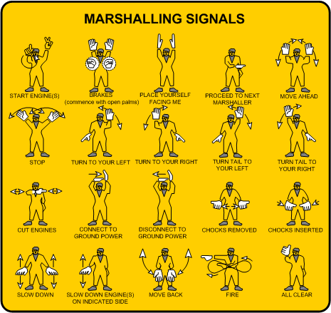
Marshallers normally position themselves forward of the left wingtip, within view of the pilot, and they will use illuminating lights at night. Note that the engines of multi-engine aircraft are numbered left to right (pilot’s perspective), beginning on the outer engine on the aircraft’s left wing.
Mountain Flying
Mountain flying presents high risk. Never fly in the mountains without extensive pre-flight planning and a thorough weather briefing. Here are some rules of thumb derived from Tips on Mountain Flying published by Transport Canada, Aviation Safety:
- Flight routing should be arranged to avoid topography that could prevent a safe landing.
- Flight routing should be along populated areas and well-known mountain passes.
- Sufficient altitude should be maintained at all times so as to enable a power-off glide to a safe landing area.
- VFR Navigation Charts (VNC) should be used rather than World Aeronautical Charts (WAC) as they provide greater detail for air pilotage; the routing, including ground clearances, should be carefully studied before flight.
- When faced with a sea of mountains, believe your compass (bearing in mind compass irregularities) as it may be your only means of getting out of trouble.
- Do not fly when the winds at or below mountain peak level, or at your intended cruise altitude, are above 30 KTS. Winds above 20 KTS should be avoided also.
- In anticipation of possible downdrafts, always cross a mountain ridge at a 45° angle so as to allow a turn away from the ridge.
- Know the wind direction at all times, and be on the lookout for changes in wind direction and velocity.
- Never fly in the vicinity of abrupt changes in the terrain, such as cliffs or ridges as they can be associated with severe turbulence.
- In anticipation of downdrafts and severe turbulence, cross mountain ridges at maximum altitude, and never with less than 1500’ separation.
- Anticipate downdrafts on the leeward side of mountains, and updrafts on the windward side; anticipate downdrafts between 1500’ and 2000’ per minute.
- Do not panic if a downdraft is encountered; they usually cease with sufficient height above ground that will enable manoeuvring safely away. Do not count on this, however, in extremely turbulent air or in canyon areas.
- If you encounter a severe downdraft, use full power and maintain the best rate of climb speed for the altitude at which you are operating; being cautious of the stall speed, attempt to fly to an updraft or smooth air.
- Remember that the actual horizon is near the base of distant mountains; improperly using the mountain peaks as the horizon will place the aircraft in a slow-flight attitude unable to climb.
- Never fly up the middle of a canyon; instead, fly along one side or the other in case a 180° turn is required.
- If possible, fly up the right side of a canyon in anticipation of other aircraft flying in the opposite direction.
- Beware of flying up canyons, valleys, and passes where the rise in terrain could exceed an aircraft climb capability.
- Beware of flying below a cloud ceiling in mountain passes—while the cloud base could be constant, the distance between the cloud base and the ground could decrease owing to rising terrain.
Aviation Fuel Handling
The handling of aviation fuel is critical with respect to the prevention of fuel contamination that could adversely affect engine power during flight, and the prevention of fire during the fuelling process.
The risk of fire is associated with a static or stray electrical discharge during fuelling. Static electricity builds up in the airframe during flight and the landing following a flight does not allow grounding owing to the insulating effect of the aircraft tires. When the aircraft is fuelled, a grounding does occur, and any static discharge could create a fireball at the filler neck of the fuel tanks. This could occur as the nozzle from the fuel dispensing systems makes contact with the filler neck in the wing. The risk of a fire incident is increased in cold ambient temperatures.
To prevent static discharge, it is critical to ensure the aircraft is properly grounded to the fuel dispensing system, thereby preventing a spark by draining any electrical potential, and this is done by attaching the dispensing system grounding wire to the airframe—usually the landing gear.
Plastic containers should not be used as grounding cannot occur through plastic.
The company supplying the fuel is responsible for quality of the product up to the point of actual delivery, after which the operator of the airport fuel service is responsible for quality—including correct storage and handling. Regulations require that a dispensing system be equipped with an approved filter, water separator or monitor that will prevent water or any sediment from entering the fuel tanks of aircraft.
Pre-flight activity must include an inspection of a fuel sample extracted from the lowest point in the fuel system (fuel sumps). The sample must appear clear and bright, free of any solid or water contamination—water, owing to its greater specific weight, will rest at the bottom of a fuel sample. Aviation fuels absorb moisture from the air, and fuel that is cloudy or hazy usually indicates the presence of free and dispersed water.
Free and dispersed water crystals in aircraft fuel system has and will cause a forced approach, so special attention must be used in very cold weather—approved fuel additives could help in this regard. The indications of fuel icing include power reduction and rough running engine.
The use of fuel drums or cans is discouraged, but if necessary, the system of fuelling must include a proper filter, water separator, and grounding wire. Only in the event of an emergency should a clean chamois or felt be used as particles from these items can clog the aircraft’s fuel system filters and nozzles.
Emergency Locator Transmitter
The ELT is a battery-powered transmitter that will detect automatically any unusual deceleration force such as that associated with a crash and subsequently transmit a distress signal on a designated frequency.
There are currently in service two types of ELTs, the older ELTs that transmit on frequency 121.5 MHz, and the newer ELTs that transmit on 406 MHz. 121.5 ELTs used to be monitored by a dedicated satellite system, but this was phased out in 2009 and replaced by 406 ELTS, which continue to be monitored by the COSPAS-SARSAT satellite systems.
An ELT signal announces your distress and enables the satellite systems to determine your approximate position. Search and Rescue (SAR) is then alerted and use the ELT signal to home in on your location rapidly.
On every flight, ensure the ELT is armed (if practical), and ensure every passenger is aware of the ELT location and operation. ELT information should be displayed in the aircraft. After landing, check 121.5 MHz to ensure that your ELT has not been inadvertently activated.
In the event of an emergency you should of course, while airborne, transmit Mayday, squawk 7700 on the transponder, and broadcast your position. After the crash or forced landing, place the ELT function switch to ON immediately. Once the ELT is turned on, do not switch it off until you have been rescued. Satellites and rescue aircraft need a continuous transmission to locate the aircraft and home to its position.
An ELT signal can be improved by, if possible, removing the ELT from the aircraft and setting it vertically on the highest nearby point, ensuring that it remains connected to its antenna. 1 Always stay with the aircraft and set up a survival camp, and prepare signal fires or some other means of attracting the attention of search aircraft.2
In the event that no emergency exists—e.g., you have conducted a precautionary landing to wait out bad weather—make attempts to contact overflying aircraft or Air Traffic Services. If not successful, switch on the ELT one-hour after the expiry of your flight plan or itinerary, as this is when the search for an overdue aircraft will begin. The ELT transmission in such cases will lessen the costs of the search and upon arrival of the search aircraft you can contact them via radio and advise of your intentions.
An ELT is only as good as the batteries. The replacement of batteries must be in accordance with the manufacturer’s instructions. ELTs should only be tested in the first five minutes of every hour.
To avoid false alarms, always switch OFF the ELT whenever it is removed from the aircraft. Disconnect the batteries if the ELT is being shipped. In the event of an inadvertent broadcast, advise Air Traffic Services that there is no emergency.
Medical Factors
Hypoxia
Lack of oxygen in the body. The most important thing to remember is that the victim of hypoxia is not aware of his or her condition. The effects are progressive with altitude: lassitude and indifference, belligerence or euphoria, including loss of aircraft control, reduced vision, confusion, inability to concentrate, impaired judgement, slowed reflexes, and eventual loss of consciousness. Symptoms typically appear at 14000’, including the potential loss of aircraft control at 16000’, and unconsciousness at 18000’. At an altitude of 50000’ the time of useful consciousness following a sudden loss of cabin pressure—i.e., the time required to recognize the problem and take corrective measures—is about 15 seconds. Nevertheless, at 10000’ there is a definite but undetectable hypoxia. Prevention: fly above 10000’ for duration of less than 30 minutes, or wear oxygen. At night, hypoxia can impair vision at 5000’, so it is recommended that oxygen be worn at night above this altitude.
Carbon Monoxide Poisoning
Susceptibility increases with altitude. Symptoms include sluggishness and warmness, intense headache, throbbing temples, ringing in ears, dizziness, dimming of vision, vomiting, and eventual death. If symptoms are noticed, turn off the heat and open a vent.
Decompression Sickness
The build-up of nitrogen bubbles in different parts of the body when they come out of solution as a result of a rapid pressure decrease. The risk is greatest in flight operations above 20,000’ (Cabin Pressure Altitude). The formation of bubbles in the lungs or the brain could give rise to chest pain and/or collapse. If symptoms include dull, sickening pain, an immediate descent to lower altitude is required.
Vertigo
Spatial disorientation—loss of bearings or confusion of sense of position and movement that occurs with reduced visual reference (clouds, fog, snow, etc.).
Alcohol and Drugs
Do not fly under the influence of drugs or alcohol. It is illegal to fly within 8 hours of consuming alcohol. It is best to allow at least 24 hours between the last drink and takeoff time, and at least 48 hours recovery from excessive drinking. The following appears in the Aeronautical Information Manual (AIM 3.11):
Alcohol is selectively concentrated by the body into certain areas and remains in the fluid of the inner ear even after all traces of alcohol in the blood have disappeared. This accounts for the difficulty in balance that is experienced in a hangover. Even small amounts of alcohol (0.05%) have been shown in simulators to reduce piloting skills. The effect of alcohol and hypoxia is additive and at 6000 feet ASL . . . the effect of one drink is equivalent to two drinks at sea level. The body metabolizes alcohol at a fixed rate and no amount of coffee, medication or oxygen will alter this rate.
With respect to drugs, do not fly within 24 hours after taking antihistamines, 48 hours after taking sulpha drugs, and 4 weeks after taking tranquillizers.
Anaesthetics
After spinal or general anaesthetics, do not fly until your doctor says it is safe; while it is difficult to generalize about local anaesthetics, common sense requires waiting 24 hours before flying.
Blood Donation
Donation of blood disturbs body circulation for several days, which may impair flying; for this reason, an active pilot should avoid blood donation; if blood has been donated, a pilot should not fly for 48 hours.
Performance Graphs
Included below is a series of generic performance graphs that are based on various aircraft types and address various performance situations.3 The idea here is to get familiar and efficient with a variety of performance graph formats.
Remember that when you begin with a performance graph, it is critical that you get a general idea of how information is input into the data, but also read very carefully the notes, limitations, or conditions that appear usually at the bottom of the graph.
Table 1—Accelerate-Stop Distances
The accelerate-stop computation determines prior to takeoff the distance required to accelerate the aircraft to a specific speed, and then abort the takeoff and subsequently bring the aircraft to a stop. As will be recalled from the examination of the regulations governing Commuter Operations, a takeoff is prohibited if the required accelerate-stop distance (ASD) exceeds the accelerated stop distance available (ASDA) at a particular runway.
The ASD table for the Piper Seneca is depicted below:
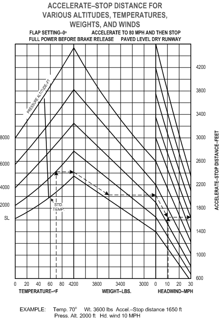
The use of the graph is straightforward. Enter from the bottom left with temperature and intercept the appropriate pressure altitude line for the departure airport; from there, move the pencil horizontally to the right until you intercept the first index line for aircraft weight (the index is associated with 4200 lbs.). From there, move parallel to the weight lines (descending to the lower right) until you intercept the vertical weight line appropriate for your departure, and from this intercept, move horizontally to the index line for headwind (the index is associated with 0 wind). From this index move parallel to the descend lines until you intercept the vertical wind line for your airport, and from this intercept, exit the graph at the ASD distance values, moving your pencil horizontally.
Note the conditions established for the ASD calculations. The flap setting is 0°, full power is developed prior to brake release, and the runway is dry and level. The ASD is for an acceleration to 80 MPH and then stop—80 MPH would be V1 or decision speed, you would think, but this would not necessary the case, for example, during a departure from a 9000’ runway.4
Table 2—Cruise Power Settings—65% Power
This graph below provides the data only for 65% power settings, so we can presume we would see additional graphs in the Pilot Operating Handbook for 55% power and 75% power.
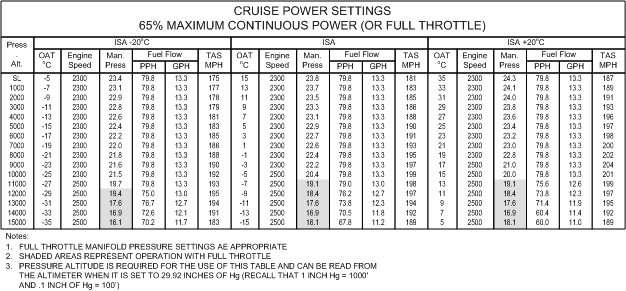
There are no surprises in the Notes section, but it can be seen that temperature is input on the basis of ISA or ICAO Standard Atmosphere temperatures. So it is required, therefore, that you determine the current relative temperature that is applied relative to ISA, whether you are 20°C less that ISA, at ISA, or 20°C more than ISA. It would, of course, be rare to fit precisely into these three categories, so you must be prepared for interpolation. For some of the items—e.g., fuel flow—interpolation is easy as there is little variation between the categories, but for others, you will have to do some math based on the calculation of percentages.5 For example, if the question to be determined is the TAS in MPH for 8000’ PA, with ISA+10 conditions, you can see that the spread between ISA and ISA+20 is 7 MPH (202-195). Since ISA+10 is 50% of the values depicted in the graph (ISA and ISA+20), you must take 50% of the 7 MPH and add this to 195 (or subtract this from 202).
Table 3—Normal Takeoff Distance—Flaps 20°
Below is an interesting graph with a whole bunch of conditions and notes, so you want to read very carefully the data that appears at the bottom of the graph.
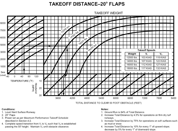
You enter this graph at the bottom left corner with temperature, noting that we must convert °C to °F. We then proceed up to intercept the Pressure Altitude lines which rise from the left side of the graph. From this intercept we proceed to the right to indicate the applicable Takeoff Weight line. Now, from this intercept, we proceed downward to the wind-adjustment lines—if the winds are calm we proceed from here directly to the distances published at the bottom of the graph, but if we are faced with a headwind component, we must proceed directly parallel to the wind lines in accordance with the headwind component MPH value, and from this intercept fall down to distance. Vr and V2 speeds are provided in the insert.
Table 4—Takeoff Distance—Flaps 8°
%20Flaps%208%20degrees.gif)
Note that this graph has reference lines, from which you move “up or down” or “left or right,” depending on the takeoff conditions. So, from the intercept of Pressure Altitude and Temperature, you migrate to the right to the Gross Weight Reference Line; if the aircraft gross weight is less than 13000 lbs. you must fall off to the lower left and if over 13000 lbs. you travel up and to the right (parallel to the Gross Weight curved lines), and continue until you intercept the actual Gross Weight lines (vertical). Then, from the Gross Weight intercept, you move to the Wind Reference Line—from here you use the same technique. Note with respect to the Gradient Percentage Reference Line you either move up parallel to the solid lines (in the event of a down-slope runway surface) or down parallel to the broken lines (in the event of a up-slope runway).6 From the Gradient Percentage intercept you move parallel directly to the far-right Takeoff Distance number—but only if the Anti-skid system is functioning—“On”—during the takeoff. Alternatively, if Anti-skid is Off then you must stop at the first line, and then proceed upward and to the right to read the increased takeoff distance.7
Consider the following question: A pilot plans for departure off a 6000’ runway. The pressure altitude is 7900’, the temperature 50°F, there is a 30 KT headwind, the runway has a 2% up-gradient, and the anti-skid selected ON. What is the maximum weight for the departure?
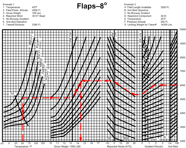
Here is the solution if all of the above conditions remain, but the wind switches to a 10 KT tailwind:
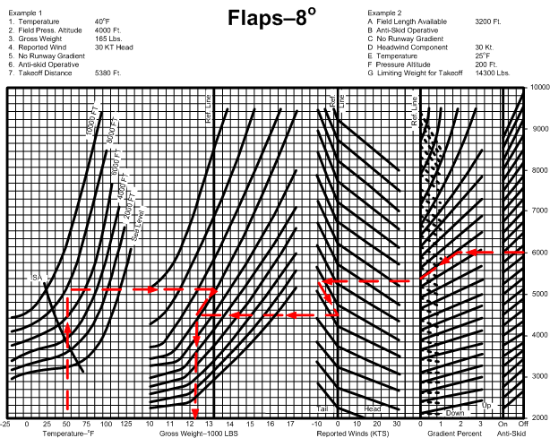
Note the tailwind must provide a penalty with respect to weight owing to a decreased performance.
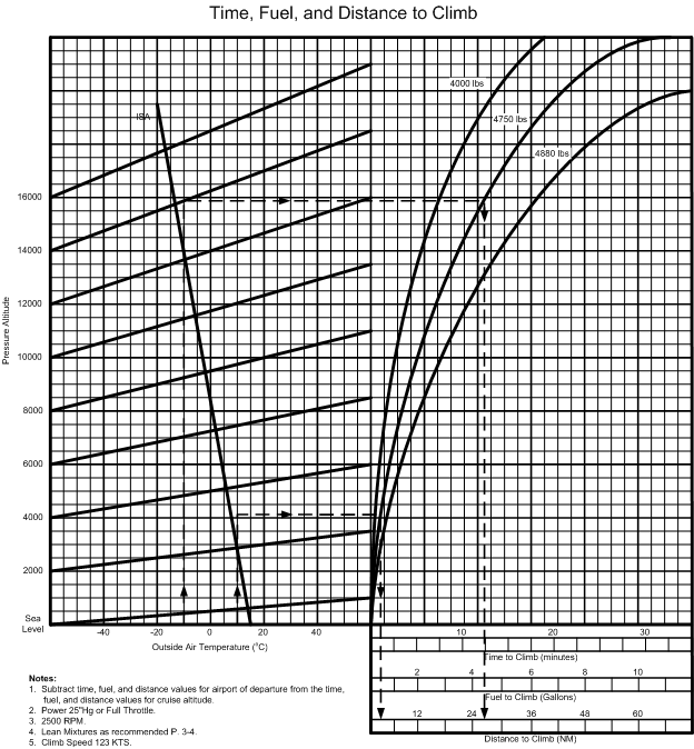
Table 5—Time, Fuel, and Distance to Climb
The graph shown below is very similar to the Table 3, the only note is that you must continue the last vertical line downward (from the intercept of the weight lines) to read time to climb, fuel to climb, and distance to climb.
References :
1 Raising the ELT 8’ will increase its range by 20% to 40%. Additionally, by placing the transmitter on a piece of metal such as the aircraft wing will provide reflectivity and will extend the transmission range.
2 If you land in an uninhabited area, the best course of action is to stay with the aircraft and the ELT. The idea here is that an aircraft is far easier to see than people are. Make all efforts to make yourself visible from the air—i.e., have smoke, flares, signal fires, etc., ready to attract attention.
3 The formats associated with these graphs do not appear in From the Ground Up—reference to the From the Ground Up graphs is included in the study questions that appear at the end of this section.
4 The interesting thing about this graph is that it initially appears far more complicated than it actually is, owing I think to the angled lines and the multiple scales.
5 With respect to performance tables, the question always arises as to how precise you must be. It is difficult to answer this as you want to be as precise as you can. One suggestion, however, is to look at the choices presented by the examination, and determine what sort of “spread” exists in the answer values.
6 Runway Gradient Percentages are published in the Canada Flight Supplement under RWY DATA.
7 The incorporation of anti-skid on this graph does not relate to aircraft performance on takeoff, but instead relates to aircraft performance with respect to the calculation of ASD (see P.107)--the ability of an aircraft to come to a stop within available runway distance after accelerating to V1 (decision speed). The required ASD will be greater with the anti-skid system not functioning (less effective braking performance).