.jpg)


AIRFRAMES, ENGINES, AND SYSTEMS—PART II
- AIRFRAMES, ENGINES, AND SYSTEMS—PART II
Definitions
- Power is the rate of doing work.
- One horsepower is the amount of work done to raise 33,000 lbs. 1 foot in the air during 1 minute.
- Indicated horsepower is the power developed within an internal combustion engine.
- Brake horsepower is the power that remains after friction and other losses.
Engine Types and Characteristics
Radial Engines
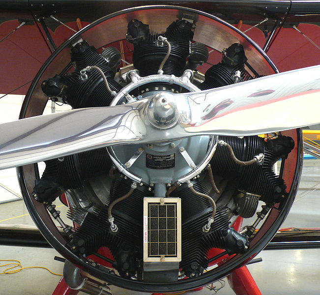
- Engines are “barrel” shaped.
- Engines have odd number cylinders.
- Advantages of radial engines: easy to work on.
- Disadvantages of radial engines: high parasitic drag and poor visibility.
In-Line Engines
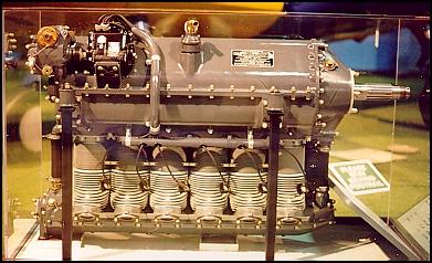
- Typically found in vintage aeroplanes.
- Advantages of in-line engines: provide very good visibility.
- Disadvantages is that there is a limit to the number (six) of cylinders owing to excessive length of crankshaft.
Horizontally opposed
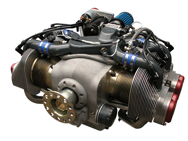
- These engines are the most common in general aviation.
- They have two banks of cylinders, opposed on crankshaft.
- There are an even number cylinders.
- They provide good visibility and relatively low drag.
Parts of an Engine
The shell of an engine is referred to as the crankcase; the crankcase has at its centre the crankshaft, which runs longitudinally through the crankcase and is connected to the propeller at the front end of the crankcase; affixed to the crankcase are the cylinders which contain the pistons; the pistons move up and down in the cylinders and this movement, caused by the timed explosion of an air/gas mixture, is the source of engine power; the explosions in the cylinders are caused by the timed spark on the ends of the spark plugs; the sparking of the spark plugs, in turn, is caused by the magnetos which are connected to the rear of the engine in what is referred to as the accessories box; as the pistons move up and down, the introduction and exhaust of the air/gas mixture is controlled by the timed opening and closing of valves located at the top or “head” of the cylinders; the timed movement of these valves is controlled by the camshaft which runs parallel to the crankshaft inside the crankcase; between the valves and the camshaft is a valve-operating mechanism; the pistons are connected to the crankcase by connecting rods; and the mixture of the air/gas mixture prior to entry into the cylinders is an induction system—usually a carburettor or fuel injection system; between the carburettor and the cylinders in the intake manifold, and as spent gases exit the cylinders they pass into the exhaust manifold and out the exhaust pipe.
The bore of a cylinder is its diameter, while the stroke of a piston is its repetitive movement from upper-most position—referred to as top-dead-centre—to its lower-most position—referred to as bottom dead centre.
Four Strokes of an Engine
The production of power in an engine is based on the movement of the pistons which can be broken down into the follow strokes:
|
Induction stroke |
Piston moves down with intake valve opened and exhaust valve closed. |
|---|---|
|
Compression stroke |
Piston moves up with both valves closed. |
|
Power stroke |
Spark plugs fire forcing piston downward, with both valves still closed |
|
Exhaust stroke |
Piston moves up with intake valve closed and exhaust valve open. |
Timing
Timing of an engine is associated with the firing of the magnetos and the opening and closing of valves; the timing is controlled by the camshaft, which rotates ½ the speed of crankshaft.
An AME (Aircraft Maintenance Engineer) can control the timing of an engine by adjusting the timing of the valves; the term valve lead is the opening of valves early (with valve lead set on the exhaust valve, for example, pressure from the end of the power stroke can be used to push-out spent gases; valve lag is the closing of valves late (with the valve lag of the exhaust valve, the end of the exhaust stroke can be used to facilitate the induction of fresh air/gas mixture; valve overlap is where both valves open simultaneously—for, example the exhaust and intake valve are both opened just prior to induction stroke to facilitate engine cooling.
Cooling
Most general aviation engines are air-cooled, whereby ram air enters the engine cowling from the front, and is circulated around the cylinders using baffles; the baffles surround the cylinders in the form of a light metal box structure that control and maximize the movement of cool air.
With higher performance aircraft that are more tightly cowled, the quantity of air moving through the baffles can be controlled by the pilot via cowl flaps, which are like reverse air scoops; the cowl flaps are opened during taxiing or during climbs to increase the volume of air movement , and are closed to reduce drag during the cruise phase.
Engine heat from cylinders is dissipated by fins that form part of the cylinder outer wall.
Oil
There are four functions of engine oil: cooling, sealing (pistons), lubrication, flushing (cleaning).
Pilot rule: Oil types cannot be mixed; for example, when oils contain additives (detergents and dispersants, etc.) only oil of the same type should be added.
Oil is graded by viscosity (resistance to flow, stickiness); the higher the viscosity, the smaller are the changes in the viscosity of the oil owing to temperature changes.
Three systems for grading viscosity are used:
- S.A.E. Number (Society of Automotive Engineers).
- Saybolt Universal Viscosity.
- US Grade
The formula to translate the oil grades: Saybolt Viscosity (100, for example) equals 2 times the S.A.E. number (50). The U.S. Grade is the Saybolt Viscosity plus 1000 (1100).
The type of oil to be added to an aircraft can be determined by the pilot by reviewing preceding maintenance entries in the aircraft Journey Log.
Oil temperature should be regularly monitored in the cockpit, as an indication of engine health. The oil temperature gauge probe is located where the oil enters the engine. If the oil gets too hot, viscosity is lost and engine parts lose their protective film of oil; if the oil is too cold, the thick oil cannot flow through engine passageways, and oil functions are impaired.
Oil pressure monitors pressure of oil supplied by the oil pump. It must be checked right after start,1 and during operations.2
Oil pressue and temperature gauges provide redundancy and a means of verifying engine trouble; a loss of oil pressure on the gauge may indicate engine trouble but it may also indicate an erred reading on the instrument itself; but a loss of pressure indication, combined with an increased temperature indication means a forced landing is imminent.
There are two types of oil systems: Wet Sump—oil supply kept in sump or pan under crank case—and Dry Sump—oil supply contained in separate tank (aerobatic aircraft).
Every flight should be preceded by a check of engine oil levels.3
The first flight of the day should include an examination of the oil filter for security (of the safety/lock wiring) and leaks.
Fuel and Fuel Systems
An ideal fuel is a fuel that when ignited produces a slow, smooth burn with slow, even expansion (not explosion); this quality is a “high octane rating.”
The term "detonation" denotes an undesired condition associated with the rapid instantaneous explosion of fuel with too low an octane rating; it over stresses engine parts, causes overheating, warps valves, and damages pistons (major bad!).
Fuel is rated on its portion of Octane to Heptane, expressed as percentage. Octane denotes any substances in the fuel that have minimum detonation qualities, while Heptane denotes any substances that have maximum detonation qualities.
E.g.: 73 Octane: 73% Octane, 27% Heptane.
Octane ratings go as high as 100, after which they become “Performance Number.”
Fuel grades are usually denoted by two numbers (e.g., Grade 80/87 or Grade 100/130). The first number is the octane rating at lean mixture, and the second is the octane rating at rich mixture.
Pilots identify octane by fuel colour—Red: Grade 80/87; Green: Grade 100/130; Blue: Grade 100/130 LL (low lead); Purple: Grade 115/145. Both MOGAS (automobile fuel) and kerosene (jet fuel) are clear (straw).
Rule: If the Pilot Operating Handbook recommended fuel is not available, use a higher Octane.
Pilot Mixture Control
Leaning the fuel/air mixture is a normal flight procedure required of the pilot as the aircraft is continually changing altitude that will cause a change in the fuel/balance.
Caution during fuel leaning must be exercised, as the improper setting of the fuel/air mixture can be disastrous for the health of the engine.
Mixture operations are specified by the aircraft and engine manufacturer and these instructions are relayed to the pilot in the Pilot Operating Handbook of an aircraft.
The normal gas/air mixture is 1:15; to obtain the maximum power from an engine (as is required, for example during takeoffs and landings), the best power mixture is used whereby the amount of fuel is increased to a ratio of 1:14; to obtain the maximum economy for an engine (as would be selected, for example, during the cruise phase of flight), the best economy mixture is used which decreases the proportion of fuel to a ratio of 1:18.
These mixture operations can be undertaken using two methods, the method of choice depending usually on the engine gauges on board a particular aircraft.
If the mixture is set using the RPM gauge, the rule is as follows: maximum RPM is the setting for best economy mixture, while a mixture set slightly rich of maximum RPM (such that the RPMs drop is perceptible) is best power.
The EGT (Exhaust Gas Temperature) gauge provides a more precise means of setting the mixture: lean mixture to peak EGT; then enrich by 25° F (cooler) for best economy mixture or 100 ° F (cooler) for best power mixture.
Here are some rules concerning the setting of the mixture control:
- set the mixture to full rich whenever manoeuvring on the ground—this provides additional engine cooling;
- set the mixture to full rich whenever climbing, also for cooling;
- set the mixture to best power or best economy whenever levelling at an altitude;
- always give priority to the aircraft or engine manufacturer’s requirements as described in the Pilot Operating Handbook, especially during takeoffs and landings.
It should be noted that, owing to the extreme risk associated with fuel leaning in flight, LangleyFlyingSchool has established very specific rules and procedures for leaning, which specify that the mixture must not be leaned below 4,000’ ASL. For more information see LangleyFlyingSchool’s Flight Training Handbook.
Fuel Systems
There are two types of fuel systems: Gravity feed —high wing aircraft—and fuel-pump feed —low wing aircraft (mechanical & electric).
Always carefully determine fuel quantity before flight; never trust fuel gauges; always dip tanks; and remember there must be 30 minutes of fuel in your tank when you land during the day, or 45 minutes when you land at night.
In flight with multiple fuel tanks, manage fuel carefully; poor fuel management by the pilot related to multiple fuel tanks has been the cause of many accidents. For additonal reading, see an accident summary related to improper use of aircraft fuel slectors.
Always study an unfamiliar aircraft’s fuel system prior to takeoff—be sure you know what to do in the event of an emergency and you will not have time to consult the Pilot Operating Handbook when the emergency occurs.
Always be especially sure of the vital actions to take in the event of an engine fire; the Pilot Operating Handbook procedure for dealing with this emergency must be followed with complete accuracy so as to minimize the damage associated with an engine fire.
Special Considerations associated with Fuel
Draining the fuel sumps before flight to examine fuel for contaminants, 4 especially water (water is heavier than fuel and therefore sinks to the bottom of fuel tank where the sumps are located).
Checking fuel colour to determine fuel grade.
Grounding aircraft during refuelling to prevent static discharge and possible fire; always supervise refuelling.
Use of Jerry Cans should be discouraged owing to the inability to control static discharge.
Passengers are not permitted in aircraft during refuelling.
Carburettor Icing
Carburettor icing is one of the most frequent causes of unexpected engine failure during flight.
An encounter with carburettor icing is most likely when in moist air conditions and between temperatures of -5 and 30°C.; a temperature of 15°C. presents the highest risk, but the Relative Humidity must be at least 50%.
The signs of carburettor icing are the signs of a choked carburettor—slow drop in RPM (fixed-pitch propellers), or slow drop in manifold pressure (intake manifold on variable-pitch propellers).
The effects of carburettor icing are usually subtle power loss and progressive engine failure.
Their causes are vaporisation and expansion.
Vaporisation of fuel requires heat and as fuel is vaporised, heat is taken from the surrounding air; the temperature drop in the mixing chamber air can be as much as 30°C., thereby freezing any water in the air (fuel vaporization ice).
Carburettors have a venturi that is designed to create a low pressure (vacuum) that draws in the fuel; expansion of a gas causes cooling (approximately 3°C.), and moisture can freeze and collect on the throttle valve at base of venturi (throttle ice).
When faced with carburettor icing, the first response is to apply carburettor heat—this action should be the first action in engine failure just in case the cause of trouble is ice (if carburettor heat is not applied immediately, usable heat from the exhaust manifold may be lost as the engine cools following the failure); if there is no ice, there will be a crisp drop in RPM. If there is ice there will usually be no immediate change, but this will be quickly followed by engine roughness as water from the melted ice is ingested into the induction system.
The two-minute rule is used when in doubt about icing: turn the carburettor heat on for at least two minutes and adjust the mixture to maximize engine performance; remember that carburettor heat degrades engine performance as it effectively decreases the density of the air entering the carburettor.
Fuel injected engines are not affected by carburettor icing, but in addition to throttle ice and fuel vaporization ice, a third form of icing, referred to as impact ice, can adversely affect both carburettor engines and fuel injected engines.
Impact icing occurs when ice builds on the external airframe during flight, including the air-intake and filtering systems for the engine.
Excessive ice on the air-intake system will effectively choke and eventually starve the engine of airflow; for this reason the selection of carburettor heat also provides an alternate heated source of air (the air is drawn from a hot box mounted on the exhaust manifold, but the air entering the hot box is non-filtered air drawn from the engine compartment); in contrast, fuel-injected engines have an “alternate air” source which can be selected in the cockpit which draws air into the engine from an engine compartment source.
Superchargers and Turbochargers
Supercharger and Turbocharger engine design provide greater altitude performance by creating a forced induction (boost) through the use of a compressor.
Superchargers are compressors driven by the engine and mounted between the carburettor and intake manifold. Turbochargers are compressors driven by an exhaust turbine and mounted between air intake and the carburettor.
Ignition
Two independent magnetos (engine-driven generator) that generates low tension current, transforms it into high tension current, and distributes it to individual spark plugs.
Dual ignition provides safety and improved performance; failure of one will result in a 75 RPM reduction in performance (typically a 3% power reduction). Both magnetos are selected for normal flight, and this is checked by the pilot prior to takeoff using the magneto switch in cockpit (the circuits can be grounded). In the event that one magneto fails during flight, the pilot is able to disconnect the failed magneto by selectively grounding it, allowing the engine to run on the normal functioning magneto (failure to ground a misfiring magneto could cause serious damage to the engine).
Here are two rules to follow:
- Always ensure magnetos are dead during shut down.
- Never rotate the prop of an aeroplane5
It is important to know that unless the primary circuit is grounded by selecting the “off” position with the cockpit magneto switch, the engine can still fire. The off position effectively grounds the primary circuit, thereby interrupting the flow of electrical energy flow. If the grounding connection associated with the magneto switch is malfunctioning and the circuit is not interrupted, this so-called “live mag” can be extremely hazardous to anyone touching the propeller as the engine could unexpectedly start merely from physical pressure.
Electrical Power
Aircraft electrical power is derived from an alternator or generator, which provide electrical power to the aircraft systems during flight and recharges the battery. The battery, in turn, is used to start the engine and serves as a backup for electrical power should the alternator or generator fail.
Most aircraft have alternators, but some have generators; generators cannot produce sufficient electrical charge to power the aircraft systems at low RPM, while alternators provide constant power at any RPM setting.
While a generator can bring a dead battery back to life, an alternator cannot.
Electrical systems have voltage regulators which safeguard the systems from alternator or generator overload and ensures the battery is not overcharged.
The bus bar provides the arteries through which the electrical energy is distributed to the electrical circuits, which in turn are connected to the various electrical components of the aircraft.
Each circuit is protected by a circuit breaker or other type of fuse that protects the connected components from excess voltage or short-circuits.
The network of circuit breakers is usually the “push to reset” type which can be readily done during flight.
Electrical components such as radio equipment can be damaged from the voltage drop associated with engine start, and for this reason, all electrical components should be turned off prior to engine start.
Two types of electrical monitoring instruments are the ammeter, which measures the rate of flow associated with the current being produced, and the voltmeter, which indicates the voltage in the system.
An ammeter should always indicate a reading that is positive (+) of zero.
Propellers
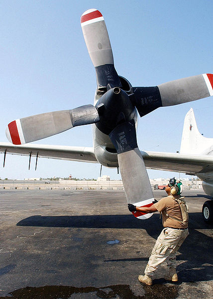
The pitch of a propeller is the distance in feet a propeller travels forward in one revolution—essentially the “bite” of air the propeller takes with each revolution. In this regard, reference can be made to a coarse-pitch propeller, which takes a “big bite” of the air during rotation and is ideal for cruise performance in straight and level flight—just as, for example, fourth gear is ideal for driving a car down a freeway—and a fine-pitch propeller, which takes a “small bite” of the air during rotation and is ideal for takeoff and landing performance (including climb performance)—just as first or second gear is ideal for driving in rush-hour traffic.
Additionally, there are two types of propellers with respect to pilot operation: constant or fixed pitch and variable pitch. In an aircraft equipped with a constant or fixed pitch, the pitch of the propeller cannot be adjusted by the pilot during flight. This is the case with the Piper Cherokee, where there are only two power controls manipulated by the pilot—the engine throttle lever, and the fuel mixture lever. In contrast, an aircraft equipped with a variable pitch propeller enables the pilot to adjust propeller pitch during flight—full fine pitch is selected for takeoffs and landings, a less-fine pitch is selected during climbs, and an even less-fine setting (a coarse-pitch setting) is selected to increase speed during the cruise portion of flight. This is the case, for example, with the Piper Seneca, where the pilot manipulates throttle levers, mixture levers, and propeller-pitch levers. With propeller-pitch levers, the pilot varies pitch with reference to engine RPMs (low RPM being coarse pitch, and high RPM being fine pitch).
Most variable pitch propellers are the constant-speed type (not to be confused with constant pitch). An aircraft equipped with a constant-speed propeller has a governor, which is a mechanism that maintains a constant RPM, despite different power settings.
Multi-engine aircraft have propellers that can be feathered during flight—in an engine fails during flight, the pilot selects the feather indent on the propeller-pitch lever and the propeller blades of the selected engine turn in line with the relative airflow, thereby minimizing drag. This feathering feature is not found on single-engine aircraft with constant-speed propellers.
References
1 Oil pressure should be indicated in the green arch of the gauge within 30 seconds of engine start, and if not the engine should be shut down and the problem investigated.
2 There are several causes that could be associated with low oil pressure during flight, but the most common are insufficient oil quantity, excessive blow-by of oil past the piston rings, oil leaks, clogged oil-pressure relief valve, or excessively high oil temperature; high oil pressure indications during flight are likely caused by inaccurate instrument indications. Generally, aircraft engines can continue to develop oil pressure with as little as two or three quarts.
3 It is a good safety rule that a pilot must always visually check oil and fuel levels prior to every departure.
4 See also discussion regarding the use of automobile gas in aircraft (Mogas).
5 The magnetos are equipped with impulse coupling, a mechanism that rapidly spins the magneto during starting. Accordingly, all that is required to start an aircraft engine is the trigger of the impulse couple (just touching the propeller could do this if the propeller is in the right position)—if the magnetos have bee left on, the engine will likely start if an impulse couple is triggered. For the same reason, if you ever have to move a propeller by hand (commonly required when moving aircraft around the ramp), be sure you rotate the propeller opposite to its normal rotation direction—this will not trigger the impulse coupling.