AIRFRAMES, ENGINES AND SYSTEMS—PART II
- AIRFRAMES, ENGINES AND SYSTEMS—PART II
Power
Power is the rate of doing work; the work of engines is measured by horsepower, whereby one horsepower is the amount of work done to raise 33,000 lbs. 1 foot in the air during 1 minute; while indicated horsepower is the power developed within an internal combustion engine, brake horsepower is the power that remains after friction and other losses.
Piston Engine Types and Characteristics
Radial Engines
Engines are “barrel” shaped; they have an odd number of cylinders; their primary advantage is that they are easy to work on, while their disadvantage is high parasitic drag and poor visibility.
In-Line Engines
Typically found in vintage aeroplanes; their advantage is that they provide very good visibility, while their disadvantage is that there is a limit to the number (six) of cylinders owing to excessive length of crankshaft.
Horizontally opposed
These engines are the most common in general aviation; they have two banks of cylinders, opposed on crankshaft; there have an even number of cylinders; they provide good visibility and relatively low drag.
Parts of an Engine
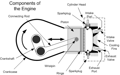
The shell of an engine is referred to as the crankcase; the crankcase has at its centre the crankshaft, which runs longitudinally through the crankcase and is connected to the propeller at the front end of the crankcase; affixed to the crankcase are the cylinders which contain the pistons; the piston move up and down in the cylinders and this movement, caused by the timed explosion of an air/gas mixture, is the source of engine power; the explosions in the cylinders are caused by the timed spark on the ends of the spark plugs; the sparking of the spark plugs, in turn, is caused by the magnetos which are connected to the rear of the engine in what is referred to as the accessories box; as the pistons move up and down, the introduction and exhaust of the air/gas mixture is controlled by the timed opening and closing of valves located at the top or “head” of the cylinders; the timed movement of these valves is controlled by the camshaft which runs parallel to the crankshaft inside the crankcase; between the valves and the camshaft is a valve-operating mechanism; the pistons are connected to the crankcase by connecting rods; and the mixture of the air/gas mixture prior to entry into the cylinders is an induction system—usually a carburettor or fuel injection system; between the carburettor and the cylinders in the intake manifold, and as spent gases exit the cylinders they pass into the exhaust manifold and out the exhaust pipe.
The bore of a cylinder is its diameter, while the stroke of a piston is its repetitive movement from upper-most position—referred to as top-dead-centre—to its lower-most position—referred to as bottom dead centre.
Four Strokes of an Engine
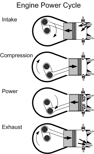
The production of power in an engine is based on the movement of the pistons which can be broken down into the follow strokes:
|
Piston moves down with intake valve opened and exhaust valve closed. |
|
|
Compression stroke |
Piston moves up with both valves closed. |
|
Power stroke |
Spark plugs fire forcing piston downward, with both valves still closed |
|
Exhaust stroke |
Piston moves up with intake valve closed and exhaust valve open. |
Timing
Timing of an engine is associated with the firing of the magnetos and the opening and closing of valves; the timing is controlled by the camshaft, which rotates ½ the speed of crankshaft.
An AME (Aircraft Maintenance Engineer) can control the timing of an engine by adjusting the timing of the valves; the term valve lead is the opening of valves early (with valve lead set on the exhaust valve, for example, pressure from the end of the power stroke can be used to push out spent gases; valve lag is the closing of valves late (with the valve lag of the exhaust valve, the end of the exhaust stroke can be used to facilitate the induction of fresh air/gas mixture; valve overlap is where both valves open simultaneously—for example, the exhaust and intake valve are both opened just prior to induction stroke to facilitate engine cooling.
Cooling
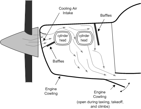
Most general aviation engine are air-cooled, whereby ram air enters the engine cowling from the front, and is circulated around the cylinders using baffles; the baffles surround the cylinders in the form of a light metal box structure that control and maximize the movement of cool air.
With higher performance aircraft that are more tightly cowled, the quantity of air moving through the baffles can be controlled by the pilot via cowl flaps, which are like reverse air scoops; the cowl flaps are opened during taxiing or during climbs to increase the volume of air movement, and are closed to reduce drag during the cruise phase.
Engine heat from cylinders is dissipated by fins that form part of the cylinder outer wall.
Oil
There are four functions of engine oil: cooling, sealing (pistons), lubrication, and flushing.
The rule for pilots is that oil types cannot be mixed; for example, when oils contain additives (detergents and dispersants, etc.) only oil of the same type should be added. Oil is graded by viscosity—viscosity being resistance to flow, or stickiness; the higher the viscosity, the smaller are the changes in the viscosity of the oil owing to temperature changes. Three systems for grading viscosity are used to grade oil—S.A.E. Number (Society of Automotive Engineers), Saybolt Universal Viscosity, and U.S. Grade. The formula to translate the oil grades: Saybolt Viscosity (100, for example) equals two-times the S.A.E. number (50). The U.S. Grade is the Saybolt Viscosity plus 1000 (1100). The type of oil to be added to an aircraft can be determined by the pilot by reviewing preceding maintenance entries in the aircraft Journey Log.
Oil temperature should be regularly monitored in the cockpit, as an indication of engine health. If the oil gets too hot, viscosity is lost and engine parts lose their protective film of oil; if the oil is too cold, the thick oil cannot flow through engine passageways, and oil functions are impaired.
Oil pressure monitors pressure of oil supplied by the oil pump. It must be checked right after start, and during operations.
Oil pressure and temperature gauges provide redundancy and a means of verifying engine trouble; a loss of oil pressure on the gauge may indicate engine trouble but it may also indicate an erred reading on the instrument itself; but a loss of pressure indication, combined with an increased temperature indication means a forced landing is imminent.
There are two types of oil systems: wet sump—oil supply kept in sump or pan under crank case, and dry sump—oil supply contained in separate tank (aerobatics aircraft).
Every flight in a piston aircraft must be preceded by a check of engine oil levels; the first flight of the day should include an examination of the oil filter for security (of the safety wiring) and leaks.
Oil Dilution
Oil dilution is the process of adding raw fuel to the oil of a cold engine as a means of temporarily reducing the viscosity of the oil and thereby making engine start easier in cold environmental conditions. Oil dilution is accomplished in the manual control valve operated in the cockpit that redirects pressured fuel into the engine oil system.
Before conducting oil dilution, care must be made to ensure engine oil is below maximum capacity and that the addition of fuel will not cause overflow. After start-up, the engine temperature must be brought up and maintained at a sufficiently high level so as to permit proper boil-off of fuel—vaporising of the fuel from the engine crankcase, etc. Boil-off should be conducted prior to takeoff, and only in accordance with the manufacture’s instructions.
Over dilution can be caused by excess dilution time or insufficient boil-off, and is indicated by an excessive drop or fluctuations in oil pressure. If an oil-diluted engine is warmed-up too rapidly and at too high a temperature, oil and fuel might inadvertently be expelled at the crankcase breather.
Fuel
An ideal fuel is a fuel that when ignited produces a slow, smooth burn with slow, even expansion (not explosion); this quality is a high octane rating. Detonation denotes an undesired condition associated with the rapid instantaneous explosion of fuel with too low an octane rating; it over stresses engine parts, causes overheating, warps valves, and damages pistons.
Fuel is rated on its portion of Octane to Heptane, expressed as percentage. Octane denotes any substances in the fuel that have minimum detonation qualities. Heptane denotes any substances that have maximum detonation qualities—e.g.: 73 Octane: 73% Octane, 27% Heptane. Octane ratings go as high as 100, after which they become Performance Number. Fuel grades are usually denoted by two numbers (e.g., Grade 80/87 or Grade 100/130). The first number is the octane rating at lean mixture, and the second is the octane rating at rich mixture. Pilots identify octane by fuel colour—Red: Grade 80/87; Green: Grade 100/130; Blue: Grade 100/130 LL (low lead); Purple: Grade 115/145. Both MOGAS (automobile fuel) and kerosene (jet fuel) are clear (straw-coloured). An important rule is that if the Pilot Operating Handbook recommended fuel is not available, use a higher Octane.
Pilot Mixture Control
Leaning the fuel/air mixture is a normal flight procedure required of the pilot as the aircraft is continually changing altitude, which will cause a change in the fuel/balance. Caution during fuel leaning must be exercised, as the improper setting of the fuel/air mixture can be disastrous for the health of the engine. Mixture operations are specified by the aircraft and engine manufacturer and these instructions are relayed to the pilot in the Pilot Operating Handbook of an aircraft.
The normal gas/air mixture is 1:15; to obtain the maximum power from an engine (as is required, for example, during takeoffs and landings), the best power mixture is used whereby the amount of fuel is increased to a ratio of 1:14; to obtain the maximum economy for an engine (as would be selected, for example, during the cruise phase of flight), the best economy mixture is used which decreases the proportion of fuel to air ratio of 1:18.
These mixture operations can be undertaken using two methods—using RPM indications or EGT indication—the method of choice depending usually on the engine gauges on board a particular aircraft.
If the mixture is set using the RPM gauge, the rule is as follows: maximum RPM is the setting for best economy mixture, while a mixture set slightly rich of maximum RPM (such that the RPMs drop is perceptible) is best power. The EGT (Exhaust Gas Temperature) gauge provides a more precise means of setting the mixture: lean mixture to peak EGT; then enrich by 25°F (cooler) for best economy mixture or 100°F (cooler) for best power mixture.
Here are some rules concerning the setting of the mixture control: set the mixture to full rich whenever manoeuvring on the ground—this provides additional engine cooling; set the mixture to full rich whenever climbing, also for cooling; set the mixture to best power or best economy whenever levelling at an altitude; always give priority to the aircraft or engine manufacturer’s requirements as described in the Pilot Operating Handbook, especially during takeoffs and landings.
Fuel Systems
There are two types of fuel systems: gravity feed —high wing aircraft, and fuel-pump feed —low wing aircraft (mechanical & electric).
Always carefully determine fuel quantity before flight; never trust fuel gauges; always dip tanks; and remember there must be 30 minutes of fuel in your tank when you land during the day, or 45 minutes when you land at night.
In flight with multiple fuel tanks, manage fuel carefully; poor fuel management by the pilot, related to multiple fuel tanks, has been the cause of many accidents.
Always study an unfamiliar aircraft’s fuel system prior to takeoff—be sure you know what to do in the event of an emergency and you will not have time to consult the Pilot Operating Handbook when the emergency occurs.
Always be especially sure of the vital actions to take in the event of an engine fire; the Pilot Operating Handbook procedure for dealing with this emergency must be followed with complete accuracy so as to minimise the damage associated with an engine fire.
Special Fuel Considerations
Draining the fuel sumps before flight to examine fuel for contaminants, especially water (water is heavier than fuel and therefore sinks to the bottom of fuel tank where the sumps are located). Check fuel colour to determine fuel grade.1 Grounding aircraft during refuelling to prevent static discharge and possible fire; always supervise refuelling.
Use of Jerry Cans should be discouraged owing to the inability to control static discharge.
Passengers are not permitted in aircraft during refuelling.
Carburettor Icing
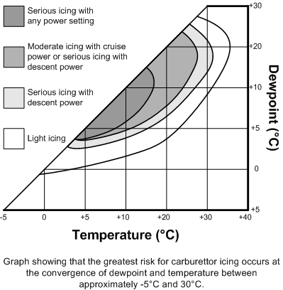
Carburettor icing is one of the most frequent causes of unexpected engine failure during flight. An encounter with carburettor icing is most likely when in moist air conditions and between temperatures of -5 and 30°C.; a temperature of 15°C. presents the highest risk, but the Relative Humidity must be at least 50%.
The signs of carburettor icing are the signs of a choked carburettor—slow drop in RPM (fixed pitch propellers), or slow drop in manifold pressure (intake manifold on variable pitch propellers). The effects of carburettor icing are usually subtle power loss and progressive engine failure.
The causes of carburettor icing are vaporization and expansion that occurs in the carburettor. Vaporization of fuel requires heat and as fuel is vaporised, heat is taken from the surrounding air; the temperature drop in the mixing chamber air can be as much as 30°C., thereby freezing any water in the air—referred to as fuel vaporization ice. Carburettors have a venturi that is designed to create a low pressure (vacuum) that draws in the fuel; expansion of a gas causes cooling (approximately 3°C.), and moisture can freeze and collect on the throttle valve at base of venturi—referred to as throttle ice.
When faced with carburettor icing, the first response is to apply carburettor heat—this action should be the first action in engine failure just in case the cause of trouble is ice (if carburettor heat is not applied immediately, usable heat from the exhaust manifold may be lost as the engine cools following the failure); if there is no ice, there will be a crisp drop in RPM. If there is ice there will usually be no immediate change, but this will be quickly followed by engine roughness as water from the melted ice is ingested into the induction system.
The two-minute rule is used when in doubt about icing: turn the carburettor heat on for at least two minutes and adjust the mixture to maximise engine performance; remember that carburettor heat degrades engine performance as it effectively decreases the density of the air entering the carburettor.
Fuel-injected engines are not affected by carburettor icing, but in addition to throttle ice and fuel vaporization ice, a third form of icing—referred to as impact ice—can adversely affect both carburettor engines and fuel injected engines. Impact icing occurs when ice builds on the external airframe during flight, including the air-intake and filtering systems for the engine. Excessive ice on the air-intake system will effectively choke and eventually starve the engine of airflow; for this reason the selection of carburettor heat also provides an alternate heated source of air (the air is drawn from a hot box mounted on the exhaust manifold, but the air entering the hot box is non-filtered air drawn from the engine compartment); in contrast, fuel-injected engines have an alternate air source that is automatic or can be selected in the cockpit—in both cases, air into the engine from an engine source underneath the engine cowling.
Superchargers and Turbochargers
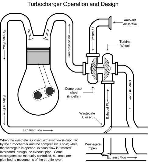
Supercharger or turbocharger equipment on an engine is designed to provide greater altitude performance by creating a forced induction (boost) through the use of a compressor
Superchargers are compressors driven by the engine and are mounted between the carburettor (or fuel control unit) and intake manifold. Turbochargers are compressors driven by an exhaust turbine and mounted between air intake and the carburettor (or fuel control unit). The effectiveness of a turbocharger system is regulated by a wastegate. When the wastegate is open, exhaust gas is vented pasted the turbine wheel into the atmosphere; when the wastegate is closed, the exhaust gas is forced into the turbine to provide turbocharging.
Ignition
Two independent magnetos (engine-driven generator) that generates low-tension current, transforms it into high-tension current, and distributes it to individual spark plugs.
Dual ignition provides safety and improved performance; failure of one will result in a 75-RPM reduction in performance (typically a 3% power reduction).
There are important rules to follow with respect to magnetos—always ensure magnetos are dead during shut down and never rotate the propeller of an aeroplane in its normal direction, as this can trigger the impulse coupling—a mechanism design to rapidly trigger the magnetos during normal starts. If the propeller must be moved by hand, rotate it opposite to its normal direction.
It is important to know that unless the primary circuit is grounded by selecting the off position with the cockpit the magneto switch, the engine can still fire. The off position effectively grounds the primary circuit, thereby interrupting the flow of electrical energy flow. If the grounding connection associated with the magneto switch is malfunctioning and the circuit is not interrupted, the magneto is said to be live. This so-called “live mag” can be extremely hazardous to anyone touching the propeller, as the engine could unexpectedly start merely from physical pressure on the propeller.
Electrical Power
Aircraft electrical power is produced by an alternator or generator, which provides electrical power to the aircraft systems during flight and recharges the battery. The battery, in turn, is used to start the engine and serves as a backup for electrical power should the alternator or generator fail. Most aircraft have alternators, but some have generators; generators cannot produce sufficient electrical charge to power the aircraft systems at low RPM,2 while alternators provide constant power at any RPM setting. While a generator can bring a dead battery back to life, an alternator cannot.
Electrical systems have voltage regulators which safeguard the systems from alternator or generator overload and ensure the battery is not overcharged.
The bus bar provides the arteries through which the electrical energy is distributed to the electrical circuits, which in turn are connected to the various electrical components of the aircraft.
Each circuit is equipped with a circuit breaker or other type of fuse that protects the connected components from excess voltage or short-circuits. The network of circuit breakers is usually the “push to reset” type that can be readily done during flight.
Electrical components such as radio equipment can be damaged from the voltage drop associated with engine start, and for this reason, all electrical switches should be turned off prior to start.
Two types of electrical monitoring instruments are the ammeter, which measures the rate of flow associated with the current being produced, and the voltmeter, which indicates the voltage in the system. An ammeter should always indicate a reading that is greater than zero.

Propellers
The pitch of a propeller is the distance in feet a propeller travels forward in one revolution—essentially the bite of air the propeller takes with each revolution.
We differentiate between a coarse-pitch propeller with its big bite—ideal for a cruise condition—and fine-pitch propeller with its small bite—ideal for approaches and takeoffs.
There are two broad categories of propellers: constant or fixed pitch and variable pitch—that is, either the pitch of the propeller is set and cannot be varied, or the pitch can be controlled to varying degrees by the pilot.
Of the variable pitch variety, there are two types—mechanical and hydraulic—based on the mechanism used to alter the propeller blades. The mechanical variable pitch propellers incorporate a direct-link control on the instrument panel, and this type is not very common in general aviation aircraft. In contrast, the hydraulic variable pitch propellers change blade pitch using oil pressure.
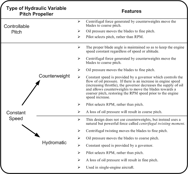
To follow this rather complicated nomenclature further, hydraulic variable pitch propellers incorporate one of three designs: controllable pitch, constant speed or hydromatic constant speed. All of these incorporate a hydraulically operated cylinder that pulls or pushes a cam connected to a gear system that operates the blades (similar to a screwdriver turning a screw).
The table below summarizes the three types of hydraulic variable pitch propellers.
Turbine Engines
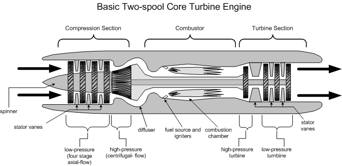
The diagrams and discussions in this section are derived from the outstanding work of Gregory N. Brown and Mark J. Hold, The Turbine Pilot’s Flight Manual (1995, Ames: Iowa State University Press).
Turbine engines operate on the basis of Isaac Newton’s Third Law, which states that for every action, there is an equal and opposite reaction. In short, the escape of hot gases at the rear of a turbine engine creates an equal and opposite reaction in the form of forward thrust.
Both turbine and piston engine utilize expanding gases, but while the expanding gas in a piston engine is but one of four piston strokes (three of which do not contribute to thrust conveyed through the propeller), the turbine engine has far greater efficiency owing to its continuous-flow condition.
Continuous flow is made possible in a turbine engine by the two components—the compressors and the turbines—each of which effectively acts like a high-tech fan and both of which are mounted on a common shaft. The compressors provide an effective air-intake function at the front of the engine. The air is compressed and then combusted (with the injection of fuel), and the expanding hot gases, as they exit with high velocity at the rear of the engine, pass through and drive the turbines. The turbines, in turn, are connected to and thus drive the compressors.
The third component of the turbine engine is the combustor—essentially the chamber in which compressed air enters, and into which fuel is continually sprayed and ignited.
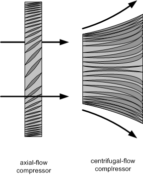
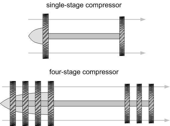
There are two types of compressor—the axial-flow compressor and the centrifugal-flow compressor. The axial compressor is shaped like a multi-bladed fan (referred to as rotor blades). Axial-flow compressors are the more efficient of the two, obtaining a compression ratio in excess of 25:1; this efficiency is derived primarily from the fact that the flow of air through axial-flow compressors essentially remains parallel to the longitudinal axis of the engine. Axial-flow compressors, however, are less durable than centrifugal-flow compressors as the rotor blades are vulnerable to impact with ingested material. In contrast, centrifugal-flow compressors essentially slingshot the air away from the longitudinal axis of the engine into what is referred to as the diffuser. The diffuser is positioned just before the combustor and serves the function of slowing the velocity of the airflow, yet simultaneously increasing its air pressure. The compression ratio of centrifugal-flow compressors is approximately 10:1.
A turbine typically has a series of compressor wheels mounted on a single shaft, and each wheel or fan is referred to as a stage (a “stage” includes the compressor wheel and the fixed stator vanes which position the flow for the subsequent compressor wheel). Each stage increases the compression of the airflow—what is referred to as a multistage compressor.
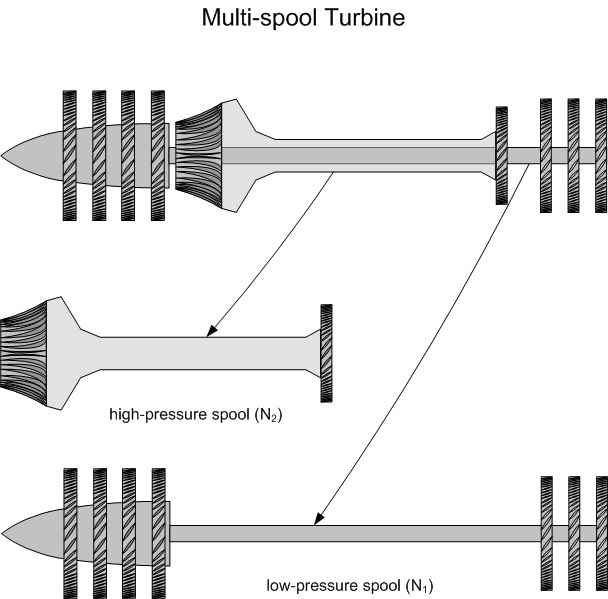
In contrast, the term multispool engine refers to turbine engines where there is more than one shaft running though the core, each shaft having it own independent set of compressors and turbines that turn at different speeds. The term spool denotes the compressor, the turbine, and the shaft that connects the two. Where two shafts exist—known as dual-compressor engines—the first compressor (most forward in the engine) is referred to as the low-pressure compressor, and it is driven by the most reward turbine. The speed at which this compressor turns is known as N1. The second compressor in the dual-compressor engine is referred to as the high-pressure compressor; it is connected to the high-pressure turbine, and the speed of its rotation is N2.
Turbofans
These basic components of turbine engines discussed above are associated with gas generator engines, core turbine engines, or turbojet engines—all basically the same type of engine. In contrast, there are major structural changes in what are referred to as turbofan and turboprop.
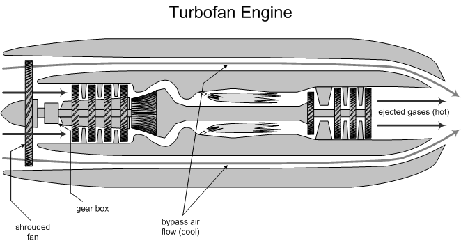
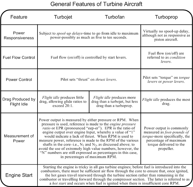
Both the turbofan and turboprop engine has the components of a core turbine engine. The turbofan engine, however, has what is referred to as a shrouded fan at the front of the engine, while the turboprop has a conventional propeller.
In the turbofan engine the shrouded fan is essentially a multi-blade propeller that is tightly fitted and enclosed in the front of the engine nacelle. The shrouded fan accelerates a much larger volume of air than a turbojet engine, a portion of which does not enter the engine core, but instead passes outside and around the core, to mix at the end of the engine with the hot gases that exit the turbines. The turbofan therefore produces bypass air which provides two important functions: firstly, the shrouded fan produces effective thrust, especially at low altitudes and airspeeds, and, secondly, the shrouded fan effectively muffles the ripping sound of the hot blast exiting the turbine core (turbofan engines are therefore much quieter than turbojet engines). A high-bypass turbofan engine is one in which the fan moves a much as four-times the volume of air that moves though the core engine; in contrast, with a low-bypass turbofan engine, the volume of air moving through the fan is approximately equal to the volume of air moving though the core engine.
Turboprops
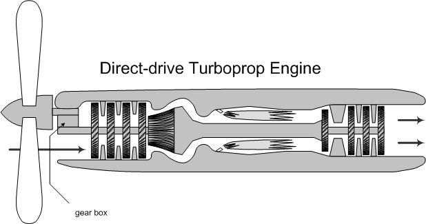
There are two types of turboprop engine, the first is referred to as a direct-drive turboprop, and the second is a free-turbine turboprop. With the direct-drive system, the propeller is connected to a shaft and turbine and the speed of the propeller is modified through a reduction gear mechanism; in the free-turbine system, the propeller is connected to what is referred to as a power turbine which “floats” in the high pressure exhaust gases in the turbine section.
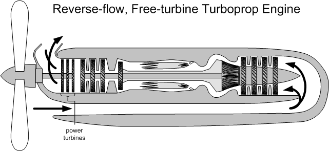
Direct-drive turboprops operate at a fixed RPM—ground idle is typically at 70% maximum power; free-turbine turboprops have lower ground-idle RPM—58% maximum power is common. The free-turbine provides easier maintenance as the power section is not physically connected to the core turbine, but are less powerful by weight and less fuel efficient when compared to direct-drive turboprops.
Compressor Stalls
A compressor stall is an abrupt interruption of the continuous flow through the compressor section of turbojet section—specifically, it is an abnormal airflow resulting from stalled airflow through the rotor blades within the compressor. With disrupted flow, compressor stalls are associated with power loss, which can vary from a momentary power drop that is often not registered on cockpit instrumentation—typically the result of a rotational stall—to a condition of complete power loss that results in a compressor surge.
Rotational stall are localized disruptions of the compressor airflow where a relatively small portion of the rotor blades experience stall flow. This produces pockets of stagnant air—referred to as stall cells—that typically rotate around the circumference of the compressor, as opposed to the normal reward directional flow through the compressor section. Rotational stalls are typically momentary, resulting, for example, from brief external disturbance (water ingestion), or they may grow within the compressor section to produce a more pervasive disruption in overall flow—what is described as a complete compressor stall and or compressor surge.
A compressor surge is therefore a complete breakdown in flow through the compressor section, and it is associated with a reversal of air flow—the inefficient compressor can no longer work against the already-compressed air rearward of the stalled section. Typically the compressor will resume normal flow characteristics once the engine pressure ratio is reduced to a level of sustainable flow, but if the conditions that initially gave rise to collapsed air flow still exist—for example, damaged compressor components as a result of ingested foreign objects such as birds, dust, ash, or grit—a “locked-in” or “self-reproducing” stall is said to exist, which can result in high levels of vibration, engine damage, and possibly total destruction.1
Reference
1 One of the best documented compressor surge—producing an engine failure—is ThomsonFly 263H, and is worthwhile searching this video on the internet.
Auxiliary Power Units
An auxiliary power unit (APU) is a small supplementary turbine engine commonly found on tail of jet and large turboprop aircraft. As the name implies, they provide auxiliary functions. Installed with a dedicated generator, they provide numerous functions on the ramp when it is impractical to power-up the main turbine engines—ground electrical power and air conditioning, for example.3
Some APU provide back-up electrical power for air operations, and most provide the independent pneumatic power (bleed air) for the starting of the main engines when a ground source of pneumatic power is not available.
Pressurization
Pressurized aircraft are those in which the aircraft’s cabin is engineered to be a pressure vessel whereby air is pumped into the cabin area so as to keep the internal pressure of the cabin as close as possible to sea level.
In the case of piston aircraft, the positive flow of air into the cabin is maintained by the compressor of turbochargers; in the case of turbine aircraft, the source is bleed air from the compressor section.
The modulation of cabin pressure is maintained by outflow valves that vary the flow of exhaust air from the cabin.
Each pressurized aircraft has a design limited maximum allowable pressure differential, referred to as maximum differential or “max diff.” This specifies the maximum ratio that can exist between cabin and outside pressure, and is commonly a limiting factor in specifying the published service ceiling of an aircraft.
The outflow valves are controlled by a pressurization controller that commonly displays in the cockpit the pressure differential, the cabin altitude, and the cabin rate of climb. Some pressurization controllers are manual, and some are automatic. All climbs and descents are calculated and the cabin rate of climb is adjusted.
Pressurization systems include a positive relief valve which is designed to release cabin pressure when max diff is exceeded, dump valves, which allow the crew to manually vent cabin pressure in the event of an emergency, negative pressure relief valves, which ensure cabin pressure is never less than external pressure, and squat switches, which, as a safety feature, ensure proper regulation of pressure during takeoffs and landings.
References
1 One potentially disastrous error to be aware of is the inadvertent adding of jet fuel to a piston-engine aircraft; jet fuel is clear in colour and has a distinct kerosene smell. The greatest risk for this occurs at Fixed-based Operators (FBOs) where refuelling is done from fuel trucks; always be sure you supervise refuelling.
2 Prolonged idling in a generator-equipped aircraft with lots of electrical devices turned on can easily drain the power source.
3 Gregory N. Brown and Mark J. Hold, The Turbine Pilot’s Flight Manual (1995, Ames: Iowa State University Press), p. 64.
.jpg)
