.jpg)

IFR Arrivals: Rules and Procedures
Content
- IFR Arrivals: Rules and Procedures
- Anatomy of Instrument Approaches
- Initial Segment
- Initial Segment—MSA Transitions
- Initial Segment—Specified Transitions
- Intermediate Segments—Procedure Turns
- Intermediate Segments—Intermediate Fixes
- Intermediate Segments—DME Arcs
- Final-Approach Segment
- Straight-in Approaches
- Circling for Landing
- GPS Minima (Straight-in and Circling)
- Missed Approach Segment
- Arrival Communications and Procedures
- STARs
- Profile Descents
- Approach Ban
- Approach Clearance
- “Open” Approach Clearance
- Frequency Change and Descents
- Descending out of Controlled Airspace
- Minimum Weather Conditions
- Contact Approaches
- Visual Approaches
- “Radar Required” Approaches
- Speed Adjustments and Restrictions
- Precision Radar Approaches
- Initial Contact with Control Towers
- Position Reporting at Controlled and Uncontrolled Airports
- IFR Procedures at Airports in Uncontrolled Airspace
- Outbound Reports
- Coffin Corner
- Pressure Considerations and Temperature Corrections
Anatomy of Instrument Approaches
In Canada, instrument approaches are developed by Transport Canada in accordance with the publication Criteria for the Development of Instrument Procedures (TP 308), and are published in the government publication Canada Air Pilot, as well as privately in the Jeppesen Airways Manual.
There are two broad categories of instrument approaches—precision approaches and non-precision approaches. There are two types of precision approaches—the ILS and Precision Approach Radar (PAR)1—and three primary non-precision approaches—NDB, VOR, Localizer (including Localizer Backcourse), and GPS.
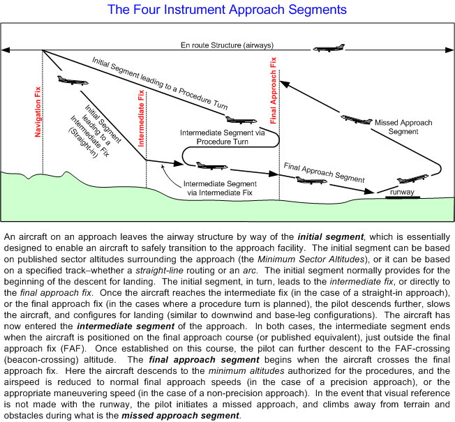
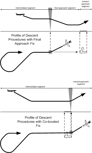
All approaches are composed of four segments—the initial, the intermediate, the final, and the missed approach. A fifth element is typically included in published approach procedures, and this is referred to as the circling element, which may for practical purposes be regarded as a feature of the final segment. Each of these segments has a standard with respect to obstacle and ground clearances.
Initial Segment
The initial segment connects the published approach the en route structure (airways). It is during the initial segment that the aircraft departs the en route structure and begins to manoeuvre the aircraft into the intermediate segment. The initial segment may contain a specified transition, an arc, or it may simply be based on the published Minimum Sector Altitude (MSA).
The standard for published initial segment altitudes is 1000’ clearance over obstacle and terrain. Where a specified transition exists, the 1000’ minimum clearance extends 4 NM on either side of the published track.
Initial Segment—MSA Transitions
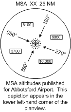
MSA transitions are provided for in all published approach procedures. They are based on data provided in a format similar to Obstruction Clearance Circles in the Canada Flight Supplement, providing minimum obstacle and terrain clearance altitudes within specified sectors surrounding the airport. In the case of MSAs, however, the radius of minimum sector altitudes extends outward 25 NM, and are based on a specified published navigation aid—typically the Final Approach Fix, where this exists for an approach. When an MSA transition is used for the initial segment of the approach, the pilot must first determine that the aircraft is positioned with the specified 25 NM radius—using GPS or DME data, a position fix, or radar services. Once this is determined, the pilot may safely descend from the altitudes specified for an airway to the minimum altitude specified for the sector in which the aircraft is positioned. The MSA data that appears on Abbotsford Airport approach plates appears below.
Initial Segment—Specified Transitions
While MSA transitions are published for all approach procedures, specified transitions appear on selected approach plates, especially busy airports. There are two types of specified transitions—those with published straight-line tracks, and those with published arcs. Arcs are simply “curved” tracks, and will be discussed below.
Straight-line transition tracks appear on approach plates in a format similar to en route airways. The pilot is provided with track orientation, distance, and minimum altitude data. They provide track guidance either to the Final Approach Fix, from which a procedure turn may be flown, or to what is referred to as an Intermediate Fix, where the procedure turn may be skipped or by-passed in the approach sequence, allowing the pilot to navigate directly to the final approach course. Powell River (above) provides an example of a transition directly to the Final Approach Fix. Transition via the AGGUA Intersection—which is published on the en route charts as an intersection on V347 (N50 15.3 W124 59.9)—would be referred to as the “Aggua Transition.” From AGGUA, a track of 123° is flown, eventually leading directly to Powell River NDB. From the 14000’ MEA of V347, a pilot conducting an approach using this transition is authorised to descend to 7400’, providing a slight advantage over the MSA minimum values. In contrast, the “Comox” transition via the Comox NDB permits a descent to 4000’. The Comox transition also appears on the en route charts as airway A16.
In the case of the Powell River transitions—or in the case of any other straight-line transition that leads directly to the Final Approach Fix (FAF)—a procedure turn must be flown after arriving at the FAF in order for the pilot to manoeuvre the aircraft onto the final approach course. The crossing of a FAF for the purpose of entering a procedure turn marks the end of the Initial Segment, and the beginning of the Intermediate Segment. That is to say, the procedure turn is, in these types of approaches, the Intermediate Segment.
Intermediate Segments—Procedure Turns
The procedure turn, then, is an intermediate segment procedure that enables the pilot to self-navigate to the final approach course. The pilot can normally approach the FAF from any direction, and then, conforming with the published altitude and heading data depicted on an approach plate, manoeuvre the aircraft so that it is established on the final approach course, tracking towards the FAF and subsequently the runway.
It is during the procedure turn that the aircraft speed is reduced, the prelanding checks completed, and the aircraft established in a landing configuration. Once the FAF is crossed, the aircraft continues onto the Final Approach Segment toward the runway, and either a landing or missed approach is conducted. The above depiction shows the four basic procedure turns commonly flown in Canada. There are other variations on these basic patterns, but they all generally serve the function of getting the aircraft configured on the final approach course within predictable distance from the FAF. The type of pattern used depends on the position of the aircraft as it approaches the FAF—the standard procedure turn, for example, would be used by a pilot approach the fix from, in the above example, the eastern quadrants, while the racetrack would serve the pilot approaching the fix from the eastern quadrants, and so forth. Additional procedure turn patterns appears in various IFR publications, and it should be noted that names of the procedure turn patterns vary somewhat between Canada and the U.S.
It must be kept in mind that procedure-turn manoeuvres are quite unlike holds, in that, while hold-entry procedures are specified in the CARs, procedure-turn manoeuvres are not. Essentially, there are perhaps a dozen different procedures that are practised in Canada and the U.S., and the pattern for a procedure-turn manoeuvre is essentially at the discretion of the pilot (or the company, in the case of commercial IFR operations). There are, however, specified parameters for published procedure turns that the pilot must conform to, irrespective of the specific pattern flown.
The depictions above provide an example of how procedure turns are presented in Canada Air Pilot, and how the parameters are interpreted.
To begin with, note that procedure can only be conducted on one side of the specified final approach course. This is indicated by the direction of the barb. In this case, the procedure turn must be completed to the south of the published final approach course of 090°.
Secondly, note that there is a published limit with respect to the distance from the FAF within which the procedure turn must be completed. In this case, the manoeuvring must be accomplished no further than 10 NM from the Alpha NDB.
Finally, note that the aircraft must remain at or above the published minimum altitude during the procedure turn. In this case, the aircraft cannot descend below 2500’ ASL until established inbound on a 090° towards the Alpha NDB. Only when the aircraft is established on the final approach course can a descent be commenced to the minimum altitude for crossing the FAF (beacon-crossing altitude). As a standard reference, note that the procedure-turn depiction includes the published 45° offsets from the final approach course—in this case, 045° and 225°. The 45° offsets are commonly flown at some point during most procedure-turn patterns.
The publication of a procedure turn for an ILS approach appears virtually identical to that of an NDB approach indicated above. With an ILS approach plate, the depiction includes the glidepath, which is projected up from the threshold of the runway. In the case of an ILS approach, the pilot does not normally descend below procedure altitude until the glideslope is intercepted. In the example shown above, it may be noted that there is a localizer-only approach that overlays the ILS approach. The dotted line depicts the non-precision approach descent using the ILS localizer signal only (with glideslope information). For localizer-only approaches, the beacon-crossing altitude is published—in the above example, the aircraft may descend to 1500’ once established on the final approach course. In the case of full ILS approaches (with glideslope information), the depiction includes the altitude that an aircraft tracking the glideslope should be at when the FAF is crossed—in the example above, this altitude is 1700’.
It was mentioned above that the initial segment of an instrument approach—whether the transition occurs via the MSA or a published straight-line transition—that the pilot is assured a 1000’ clearance over all vicinity obstacles. In the case of procedure turns—which is part of the intermediate segment of an instrument approach—the obstacle clearance decreases from 1000’ to 500’. Obviously, 500’ over terrain in IMC conditions is not a lot of space, so you can see that you have to be rather precise with your instrument navigation. You might think that this reduced obstacle clearance would be assured within the distance limitations published for the procedure turn—say 10 NM—and that this would apply to the entire quadrant specified for the procedure turn. Importantly, this is not the case. Instead, 500’ obstacle clearance is only assured in lopsided oval as depicted on the left.
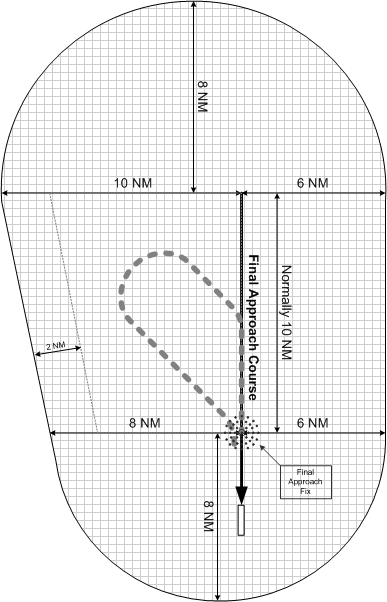
The above depiction, then, shows the dimensions of airspace surrounding a published procedure turn, outside of which, an aircraft must never stray. In this case the procedure turn is left, and therefore the aircraft is required to conduct procedure turn manoeuvring to the left of the final approach course, and above a line running perpendicular to the final approach course through the final approach fix. In fact, the shaded area includes a built-in 2-NM buffer area, and the primary manoeuvring area is no closer than 2 NM from the boundary indicated. The important point to realize is that aircraft must be maintained in close proximity of the final approach fix, and it is desired that the aircraft is manoeuvred. If an aircraft strays outside the limits of protected airspace, the published procedure turn altitude will not assure obstacle clearance.
The question arises as to how a pilot in IMC conditions reckons the aircraft’s distance from the final approach fix during procedure turn manoeuvring. Certainly, distance information provided by GPS or DME would be used when available. But the primary tool used is time. Even when distance data is available, time is used as a back up. If the aircraft is travelling at 120 KTS during procedure turn manoeuvring, and the winds are calm, it will pass 2 NM every minute. Accordingly, with a 10 NM procedure turn limit, the aircraft should travel away from the final approach fix for no more than, say, four minutes. It is critical, of course, that consideration be given to drift caused by wind.
The question arises as to how procedure-turn information is presented in Canada Air Pilot, and there are some subtle, yet important, variations to be aware of.
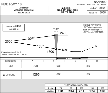
In this regard, consider the published NDB approach for Nanaimo Airport’s Runway 16.
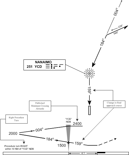
As may be noted in the depiction above, the Nanaimo procedure turn requires a right turn, rather than the left turn that is normally used. Accordingly, based on the position of the procedure turn barb, all manoeuvring must be conducted to the west of the 184°/004° track.
Also, note that the Nanaimo procedure includes a minimum crossing altitude for the final approach fix when entering the procedure turn. When a crossing altitude is published, the aircraft must not descend to the procedure-turn altitude until the aircraft is established on the procedure-turn side of the final approach fix. At Nanaimo, then, the aircraft cannot descend to 2000’ until the aircraft has passed abeam the fix outbound in the procedure turn. With most instrument approaches, however, a minimum crossing altitude is not specified, and a pilot may descend to the published procedure turn altitude immediately after the fix has been crossed, from any direction.
Lastly, note that the Nanaimo procedure includes a change in the final approach course. While the procedure turn is based on the 184°/004° track, the aircraft must accomplish a course change to 159° once the aircraft has crossed the NDB and is proceeding towards the runway in the final approach segment.
Another variation in procedure turns occurs when the final approach fix is co-located at the airport. In the case of Nanaimo, for example, the NDB is located 4.1 NM from the airport, and this is the desired approximate location of a FAF—offset from the runway so that a final approach segment may be flown. In the case of Powell River, however, the NDB is located right at the airport.
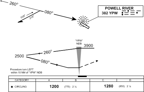
In the case of Powell River, note that the final-approach fix depiction (the cross) is missing. As is the case of all published approaches with a co-located FAF, the procedure does not have a final approach segment. Note also that there is not a published bacon-crossing altitude. Instead, the final altitude reference is derived from the minimums box, where, in the case of this approach, the aircraft is authorised to descend to 1200’ (Category A and B aircraft). This final descent is done once the aircraft has completed the procedure turn and is established on the final approach course of 080°.
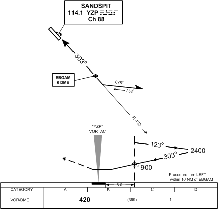
While it is common for the procedure turn to be anchored on an NDB, this is not always the case. With the Sandspit VOR/DME RWY 30 approach, for example, the FAF is a DME fix—in this case EBGAM fix is based on 6 DME from the Sandspit VORTAC on the 123° Radial. In transitioning to this approach, consideration would have to be given to means by which tracking to EBGAM is accomplished. Without waypoint navigation capability—GPS or RNAV—an aircraft could reckon its position at EBGAM only after passing the VORTAC and tracking outbound on the 123° Radial.
On occasion, the procedure turn is conducted on a facility fix other than the final approach fix. This is the case with the ILS for Cranbrook’s Runway 16. Two NDBs are located on the final-approach course for this approach, with the inner NDB, named Cranbrook, being the final approach fix, while a second NDB, located more than 16 NM up from the final approach fix is the anchor for the procedure turn.
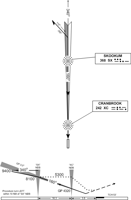
The Cranbrook ILS also demonstrates the differences between precision and non-precision approaches. Note how the procedure turn provides for a descent to 8100’ prior to crossing the Skookum NDB. From this altitude, an aircraft flying the ILS intercepts the glideslope and begins the continuous descent down to the runway threshold along the 3° glideslope. In the case of the non-precision localizer approach, an aircraft crossing Skookum can then descend down to 5300’. This altitude, in turn, is maintained until Cranbrook is crossed, after which the aircraft can descent to the published MDA.
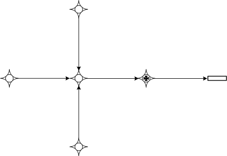
A final note concerns RNAV-GPS approaches. GPS approaches do not have procedure turns. Instead of manoeuvring the aircraft for interception of the final-approach course by reference to the final-approach fix, or a secondary facility or fix, as is the case with the Cranbrook ILS, the aircraft proceeds to one of the three waypoints which surround the final-approach course, and from one of these waypoints to another waypoint located on the final-approach course outside the final approach fix. The approach therefore appears alike a cross, with the long center post being the final approach course.
GPS approaches differ in that a pilot preparing for the procedures does not tune, identify, and set the various navigation aids that make up a conventional instrument approach.3 Instead, the waypoints that compose the GPS approach are loaded from the internal memory of the GPS black box. To load, the pilot first selects the airport, and then, in the case of multiple GPS approaches, selects the one intended to fly. Once the particular approach is selected, the pilot must then select the initial fix from which the final approach course will be navigated to.
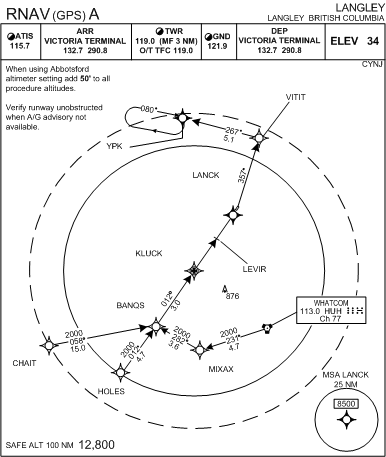
Above is a depiction of the RNAV GPS A approach for Langley Airport. The cross-shaped layout is based on the CHAIT, HOLES, and MIXAX Waypoints, with an additional transition route being provided between MIXAX and the Whatcom VORTAC. Once an approach clearance is received, the pilot can descend to the minimum altitudes published for each of these transition routes. After the first transition fix is entered the GPS incorporates the waypoints that make up the transition into the active flight plan of the GPS, and as the aircraft progresses through the transition, the GPS automatically cycles through the waypoints in the correct sequence. Interestingly, the rule for IFR approved GPS systems is that the pilot cannot manually select the waypoints that make up the approach procedure; instead, the approach (and transition) must be selected and loaded as a single entity or unit.
Another feature of GPS approaches is turn anticipation. The 90° turn that appears on the MIXAX transition, for example, when turning onto the final approach course at BANQS would not be seen on a conventional instrument approach. The GPS black box makes this turn possible, however, because it instructs the pilot when to begin a 20°-banked turn onto the final approach course. The GPS anticipates the turn.
A final note relates to the missed approach. The GPS does not automatically sequence to the first missed-approach waypoint until the pilot instructs it to do so. This is, or course, to enable the pilot to radio-navigate with reference to the missed-approach point—in the case of Langley, LANCK—during the manoeuvring for a landing in what could be marginal weather conditions.
1 A third type of precision approach—MLS for Microwave Landing System—was pursued by Transport Canada for a brief period some years ago, but has essentially been phased out of service. MLS still appears in US approach publications. With respect to PAR approaches, these only appear at military airports in Canada are therefore not generally relevant to Canadian civil aviation.
2 Flying an ILS instrument approach, for example, requires that the display for the localizer and glideslope are properly tuned and identified, with the final approach course selected, and that the FAF---typically an NDB—is also properly tuned and identified.
Intermediate Segments—Intermediate Fixes
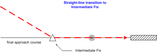
On occasion, a straight-line transition provided in the initial segment leads to a fix that is located on the final-approach course with sufficient distance from the FAF such that a procedure turn is not required. The fix associated with these types of straight-line transitions is said to be the Intermediate Fix (IF), and the intermediate segment that follows—rather than entailing a procedure turn—simply requires straight-in tracking from the IF to the FAF, and thence straight-in to the runway threshold. This by-passing of the procedure turn is shown below.
An example of Intermediate Fix that permits a straight-in Intermediate Segment is the NDB 07 approach at Abbotsford, depicted below.
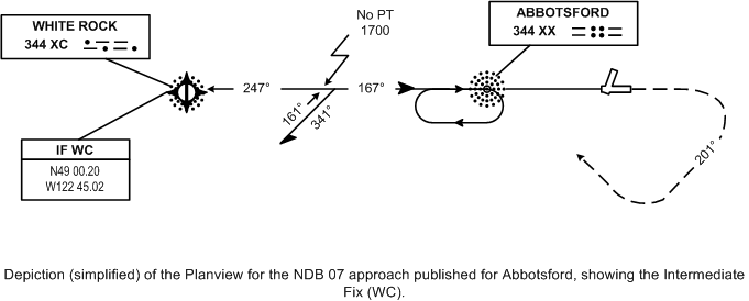
The symbol for an Intermediate Fix (IF) varies somewhat, but it is likely to be a short “crossing” line that is perpendicular to the final approach course. In the case of the Abbotsford NDB approach, for example, the IF symbol is located directly over the White Rock NDB. As can be seen, the White Rock NDB is also a Waypoint—indicated by the waypoint symbol; this appears as the Abbotsford NDB approach is also authorised for GPS overlay. Not also that the approach at Abbotsford is explicit with the notation “No PT” (for “No Procedure Turn”) referenced by an arrow just outside the procedure turn symbol (the 45° offset “barb”).
A pilot planning the Abbotsford NDB 07 approach therefore has the option of proceeding directly to the XX NDB and performing a procedure turn, or—alternately—proceeding to the WC NDB, and from there tracking 167° directly to the XX NDB for a straight-in approach.
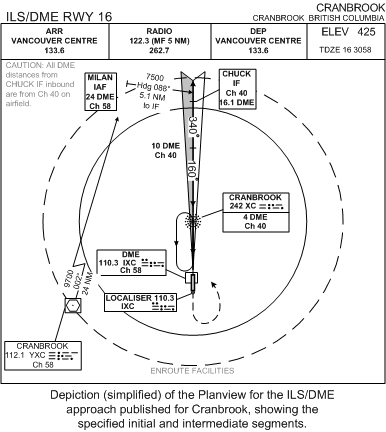
In fact, the appearance of an IF on an NDB-only approach is not very common. More often they appear in conjunction with DME facilities located on the ground, and they are frequently found on ILS approaches where DME is required.1 By way of example, consider the ILS/DME approach published for Cranbrook, which appears below:
 .
.
The IF named CHUCK appears on the Cranbrook’s ILS/DME RWY 16, but it is not featured on the ILS-only approach also published for Runway 16.
The transition to CHUCK is anchored on the Cranbrook VOR. From here, the 002° Radial is tracked for 24 DME (NM), where the aircraft is positioned at MILAN. Note that MILAN is formally noted as the Initial Approach Fix (IAF), but the Cranbrook VOR is also technically an IAF—that is, a fix that forms part of the Initial Segment for the approach. From MILAN, the pilot steers 088° to intercept the ILS Localizer. CHUCK is located further down the Localizer—specifically, 16.1 DME from the IXC. Caution must be used to differentiate the two DME transmitters that apply to the MILAN transition—MILAN is defined using the Cranbrook VOR/DME (noted as Channel 58), while CHUCK is defined using the ILS/DME (noted as Channel 40). A special notation appears on the plate warning the pilot of possible confusion in this regard.
Note that a procedure turn is not authorised on ILS/DME 16—apparent because the 45°-offset barb does not appear. The procedure-turn barb does appear on the ILS-only plate for Cranbrook, and other than the MILAN transition and CHUCK as the IF, the two approaches—the ILS/DME and the ILS-only—really do not differ.
The notation “IF” appears on all approach plates with an Intermediate Fix, but it fact multiple Intermediate Fixes can be located along a single final approach course for an approach. If more than one IF is featured on the final approach course, these will only be indicated by the crossing lines. In the case of Cranbrook, for example, a second IF appears at 19 DME—the “crossing line” is apparent abeam the notation. Multiple IF positions appear prominently on the ILS 09 approach for Victoria—no less than three: BRANY, 11 DME, and 7 DME.
Intermediate Segments—DME Arcs
In order for a DME arc transition to exist in an approach procedure, the airport must be equipped with both VOR and DME facilities. A DME arc is essentially the same as a straight-line transition track leading to an IF, except that the pilot flying an arc must navigate a curved course published at a specified distance from the DME transmitter.
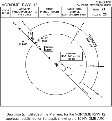
Above is a depiction of the published 15 DME arc for the VOR/DME Runway 12 approach at Sandspit Airport. The beginning of the arc is defined by a published radial—in the case of the Sandspit VOR/DME Runway 12, the arc begins on the 108° Radial—and the end of the arc is defined by the Lead Radial (LR)—in the case of Sandspit, the 303° Radial. The arc transition for Sandspit has a published minimum altitude—2700’ ASL, and a descent to this altitude can be initiated once the aircraft is established on the arc.
Specifically, navigation to an arc transition is accomplished by tracking an intercepting radial either inbound or outbound from the anchoring VOR. As the specified DME is approached—15 DME in this case, in the case of Sandspit—the aircraft is turned 90° in the direction of the arc. Once the CDI indicates a 10° deflection (see below), the course is altered 20° inward to the centre of the arc. Simultaneously, the OBS (in the case of a conventional VOR display) or the Course Selector (in the case of an HSI) is adjusted 20° in the direction of travel along the arch. The CDI will show full in the opposite direction. When the CDI migrates across the display, to again show 20° travel along the arc, the heading of the aircraft is again altered 20° toward the centre of air. This process of 20° heading change for 20° of arc-travel, is repeated until the lead radial is crossed. With lead-radial crossing, the aircraft is turned inward to intercept the final approach course. In the case of Sandspit, the lead radial is published as the 303° radial.
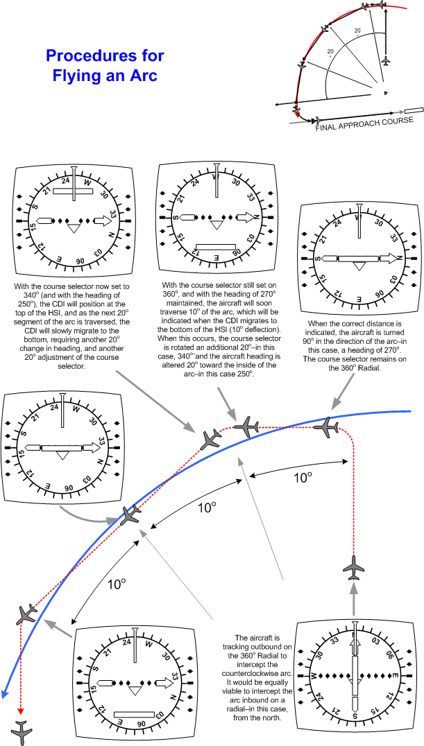
Throughout the process, the pilot monitors the DME reading. If drift is evident by excessive deviation off the target DME reading, the change in heading can be done early or deferred, as the situation may warrant. At first this process might appear extremely complicated, but in fact it is quite simple to fly once you have a little practice.
DME arcs are also provided for on IFR GPS systems, but instead of using the radials for reference in the turning sequence, the GPS black box presents the arc as a series of waypoints.
1 Another example of an NDB approach where an IF exists is Nanaimo. Here you will see the IF named ARMAC on both the NDB 16 and NDB/DME 16 approaches. ARMAC is defined using 264° Radial off Vancouver’s VORTAC.
Final-Approach Segment
The final-approach segment begins at the final-approach fix, and extends to the missed-approach point (MAP). The final-approach fix is located on the published final-approach course, and it is along this track towards the runway threshold that assured obstacle clearance is reduced in some instances to only 200’.
Some approaches lack a final approach fix, and instead, the navigation aid on which the approach procedure is anchored is co-located at the airport. Such approaches (see Power River) essentially lack a final approach segment, and the descent to the Minimum Descent Altitude (MDA) is conducted at the end of the procedure turn when the aircraft is established on the final approach course. These two variations are depicted below.
With respect to precision approaches (ILS), the aircraft is typically set up in a landing configuration by the time the FAF is crossed. The final-approach segment is therefore simply flown with the intent of maintaining the glidepath and localizer indications. At minimums (DH), the aircraft and pilot are ready for touchdown. Importantly, if satisfactory visual reference to the landing area is not established at minimums, physics require that the aircraft will continue for a few seconds in its descent, and the aircraft will descend below the published DH, but it can only continue though DH provided the pilot is in the act of discontinuing the descent—i.e., the pilot is below DH only for the purpose of initiating a missed approach. Put in another way, when weather is below minimums, the only reason why a pilot should go below DH is for the purpose of conducting an overshoot for the missed approach, and even then it should only be for a second or two.
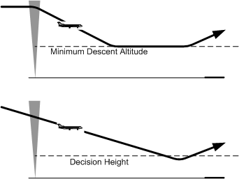
In the case of non-precision approaches (NDB, VOR, LOC, etc.), it is not uncommon for the aircraft to be configured at reduced speed in level flight when the FAF is crossed—the pilot having established the aircraft level at the FAF-crossing altitude. When the FAF is crossed, the final-approach segment typically begins with the pilot immediately initiating the last descent down to the MDA. If adequate visual reference to the landing area is not established by the time the pilot approaches MDA, the aircraft must be once again levelled off at a reduced manoeuvring speed that is similar to what is normally flown in the downwind leg during a visual landing. There is a critical difference—and this is important—between DH, for a precision approach, and MDA, for a non-precision approach. The following notation appears under Landing Minima in CAP GEN:
CAR 602 specifies that landings are governed by published DH/MDA’s. Pilots of aircraft on instrument approaches are prohibited from continuing the descent below DH, or descending below MDA, as applicable, unless the required visual reference is established and maintained in order to complete a safe landing. When the required visual reference is not established or maintained, a missed approach must be initiated. Missed approaches initiated beyond the MAP may not be assured obstacle clearance.1
This section of the CAP-GEN goes on to specify recommended visual references:
The visual references required by the pilot in order to continue the approach to a safe landing should include at least one of the following references for the intended runway and should be distinctly visible and identifiable to the pilotthe runway or runway markings;
- the runway threshold or threshold markings;
- the TDZ or TDZ markings;
- the approach lights;
- the approach slope indicator system;
- the runway identification lights (RILS);
- the threshold and runway end lights;
- the touchdown zone lights (TDZL);
- the parallel runway edge lights; or the runway centerline lights.
Keep in mind that these visual references are recommended.
Straight-in Approaches
Flying down a glidepath to the published DH is one form of a straight-in approach. If visual reference to the runway is made, the landing is completed, and if the visual reference is not acquired, the pilot of the aircraft initiates the published missed-approach procedure, and safely climbs away from terrain. In the case of non-precision approach, there is not a DH, but there is instead a Missed Approach Point (MAP). At the MAP, the pilot initiates the climb away from the MDA and begins the missed-approach procedure. Let us now examine a couple of examples of how missed-approach points are set out for non-precision approaches.
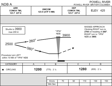
On some approach procedures the MAP is simply defined by the passage of a navigation aid. This is the case, for example, at Powell River, where the primary navigation fix for the procedure is co-located at the airport. Indication of the MAP in these types of approaches is provided in the profile view of the approach. The flat line at the bottom of the descent shows the routing of the aircraft at the MDA along the final approach course. When the NDB is crossed, the solid line is replaced by a dashed line, which depicts the aircraft in a climb as per the missed approach procedure—in the case of Powell River, the pilot must initiate a climbing right turn to a heading of 260°, and this heading is to be maintained until the aircraft reaches 2700’. After reaching 2700’, the a second right turn is conducted, and the aircraft is to proceed directly to the Powell River NDB, maintaining 3900.’
The majority of approach procedures use time to define the MAP. Based on the estimated groundspeed of the aircraft, the final-approach segment is timed to predict when the aircraft will arrive at the threshold of the runway. In the case of Nanaimo, for example, an aircraft travelling at a groundspeed of 110 KTS will require 2 minutes and 14 seconds to fly the distance of 4.1 NM that lies between the FAF and the threshold of Runway 16.
Obviously, the wind must be factored in if the determination of the MAP is to be accurate (and you want accurate). If the same aircraft is flying a headwind component of 10 KTS, it will require only 2 minutes and 29 seconds. The correction for wind must be factored in as accurately as possible, even though there is no assurance that the winds on the surface will be the same as the winds at the MDA.
Another factor to consider is the time at which the pilot should first look up from the instrument panel to check for visual reference. For the purpose of manoeuvring the aircraft for landing, a pilot might first look for visual reference approximately one minute back from the threshold. Accordingly, if the aircraft is travelling at a groundspeed of 110 KTS, the pilot should check for visual reference at approximately 1 minute, 14 seconds.
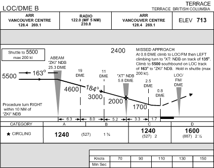
The Terrace LOC/DME B is different from the Powell River or Nanaimo approaches because DME alone is used to define the MAP. As can be seen, the published procedure for Terrace is similar to the Power River approach in that the times and distance box is blank. Instead, the pilot must look to the profile view of the approach, as well as the missed approach description, where the MAP is defined as .8 DME. Note also that the distance defined by DME is different from the distance measurements to the threshold (you don’t want to confuse the two). In fact, the DME transmitter is co-located with the localizer and fan marker at the departure off the departure end of the runway.
It is interesting that this approach does not provide a lot of time at the MDA to spot the runway. If the aircraft leaves the altitude at which 2.5 DME must be crossed—1700’—and descends down to the MDA of 1240’ at 1000’ per minutes, this will take about 30 seconds. During that 30 seconds, an aircraft with a groundspeed of 120 KTS will cross about 1 NM, leaving only 20 seconds at the MDA in level flight. Considering the precious seconds it takes to set level flight, you can see why this approach is designated not as a straight-in approach, but only as a circling approach.
Circling for Landing
In fact there are two additional variations related to the final-approach segment. On the one hand, a published procedure may provide for a straight-in approach, whereby the final-approach course is adequately aligned with the runway intended for landing; on the other hand, however, a circling manoeuvre may be required.
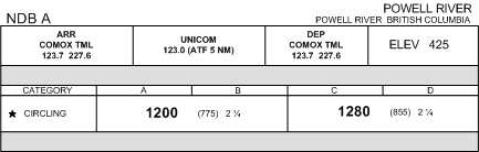
There are two general reasons why a pilot might fly a circling manoeuvre, rather than a straight-in approach. First, the pilot may not have a choice—straight-in minimum may simply not be published for the runway intended for landing. This is the case, for example, with NDB A at Powell River depicted above. The layout of this approach at Powell River does not conform with the more stringent requirements for straight-in instrument approach procedures. Thus, this approach is designated alphabetically—the NDB “A”—rather than using the runway identification number, which is the case with the NDB 07 at Abbotsford where a straight-in approach is provided.
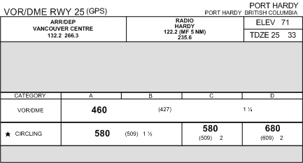
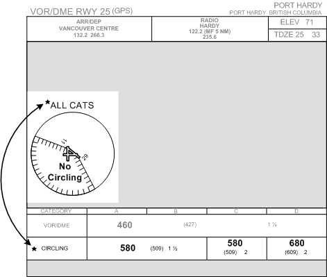
The second reason why a circling manoeuvre is performed, however, is not because of limiting features of the approach layout, but simply because the pilot may elect to do an approach on one runway, yet land at another at the same airport. For the most part, the published minima box provides a circling option for every approach that has an approved straight-in manoeuvre. This the case, for example, with the VOR/DME RWY 25 approach at Port Hardy (above), as well as the ILS RWY 16 at Cranbrook (below).
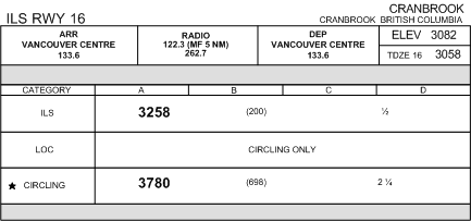
Note that the rule for prohibited descent below applies to circling manoeuvres performed off ILS procedures—the aircraft leaves the glidepath at the MDA (in the case of Cranbrook, 3708’), and does not descend below this until a safe landing is assured.
There are two additional points that are important to know with respect to circling manoeuvres. The first relates to the rather tight limits for terrain and obstacle clearance. The posted MDA for a circling manoeuvre provides only 300’ clearance over obstacles within a small radius around the runway surfaces of an airport. That leaves not a lot of space between the aircraft and obstacles when the aircraft is being manoeuvred for landing.
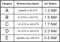
The table above outlines the arc radii within which the 300’ obstacle clearance is assured. The categories, as you can see, are identical to those used for SPEC VIS determination, and they are similarly based on the speed at which the aircraft is to be manoeuvred. As in the case with SPEC VIS manoeuvre speeds, it is important to remember that the manoeuvring speed for circling are not necessarily fixed for aircraft. In the case of Cranbrook, for example, an aircraft flying a straight-in localizer approach for Runway 16—in which the MDA is governed by circling minima—can be reduced to a much lower manoeuvring speed, when compared to the same aircraft that conducts the localizer for Runway 16, but has to circle for landing on Runway 34. In the case of the straight-in approach, the aircraft might meet Category A requirements, but in the case of circling for the reciprocal runway, the manoeuvring speed required might boost the aircraft up to Category B. Granted, there is not a lot of speed variation to play with, but it is nevertheless important to remember the tight parameters associated with obstacle-clearance protection during circling manoeuvres.
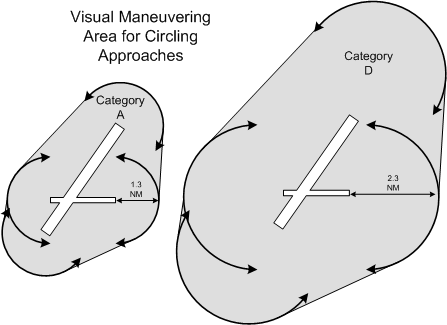
The protected radius for a circling manoeuvre—as set out by the categories listed above—is based on distance from the runway thresholds that exist at the airport. As depicted below, an arc is projected from each runway threshold, and the limits for manoeuvring are determined from the position of these arcs, as well as the tangent lines jointing them.
A second important thing to remember about circling manoeuvres is the possibility of circling restrictions. In the depiction for the Port Hardy VOR/DME Runway 25, note the circling restrictions that limit any circling to the to the north and east of the Runway 29/11 centerline. These sorts of restriction are common, especially in mountainous areas.
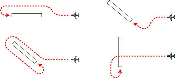
The patterns commonly used for a circling manoeuvre are outlined below. The pilot has latitude with respect to the pattern flown, so flexibility is built in. Unless there are restrictions, pilots prefer to circle clockwise so as to permit the best pilot-view of the landing areas.
Making a landing with limited visual reference is a tricky business, and you should be especially aware of illusions that may be associated with the landing environment. These are outlined below.
|
Situation |
Illusion |
Outcome |
|---|---|---|
|
Runway narrower than usual |
Too high |
Tendency to flare late |
|
Runway wider than usual |
Too low |
Tendency to flare early |
|
Runway slopes up |
Too high |
Tendency to make low approach |
|
Runway slopes down |
Too low |
Tendency to make high approach |
|
Terrain before runway is higher |
Too low |
Tendency to make high approach |
|
No lights before runway at night (Black-hole) |
Too high |
Tendency to make low approach |
|
Air very clear at night |
Closer to airport than actual fact |
Tendency to descend too early |
|
Smoggy or hazy air |
Farther from airport than actual fact |
Tendency to descend too late |
GPS Minima (Straight-in and Circling)
Just a final word on GPS approaches. For the most part, GPS minima are depicted identical to non-GPS minima, but there are some variations to point out. First, the profile view of the final approach segments often contains a series of waypoints, defined by GPS, which enable the pilot to reckon the progress of the aircraft during the approach and descent.
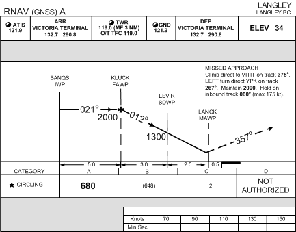
Langley appears above, and you can see that the final approach segment is made of up four wapoints—Banqs, Kluck, Levir, and Lanck—each with a different designation. BANQS has the designation of the IWP, which is the Intermediate Waypoint; because it is located on the final approach course, it has the same status as a standard Initial Fix (see p. 148). The next waypoint is KLUCK (the “chicken fix”), and is designated the FAWP—the Final Approach Waypint, identical to a Final Approach Fix. LEVIR is next, and it is designated SDWP which abbreviates Step-down Waypoint. When KLUCK is crossed, the pilot can only descent initially to 1300’, but once LEVIR is crossed, the pilot can step-down the published MDA of 680’. The last waypoint—LANCK—maps the end of the final approach segment and designates the point at which a lack of visual reference with the runway requires a missed approach; it is therefore the MAWP—the Missed Approach Waypoint.
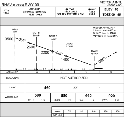
The Langley RNAV A is obviously a circling approach in that there are no straight-in minima published, and instead “circling” appears in the minima box. This is a good time to look at straight-in RNAV approaches, which contain, as you would expect, a bunch of acronyms. Below is the RNAV approach for RWY 09 at Victoria:
In the profile view, the waypoint designation are recognizably identical to Langley—IWP, SDWP, FAWP, AND MAWP—but in the minima box, however, we now see provision for LNAV/VNAV, LNAV, and, finally, circling. LNAV/VNAV refers to WAAS capabilities (see P. 54). Of course, this Victoria approach, as is the case with most GPS approaches in Canada, does not have WAAS facility and the LNAV/VNAV are not authorized nor published. The GPS lateral navigation minimum—LNAV—is published.
1 Canada Air Pilot Instrument Procedures, General Pages, Operating Minima—Landing, P. 1
Missed Approach Segment
The missed approach segment is considered to be the most critical part of an instrument approach. Perhaps most significantly, the workload is high in a missed approach, as the configuration of the aircraft must be changed (approach to overshoot), and a new sequence of navigation instructions must followed.
One of the greatest hazards associated with conducting a missed approach is referred to as the pitch-up illusion. When the aircraft is established on approach, the forces acting on the otoliths—hair-shaped cells in the inner ear that provides sensory information related to acceleration—provides the sensation of stabilized speed, based primarily on the forces of gravity. When acceleration occurs, as is the case when a missed approach is conducted and the aircraft accelerates from approach speed to climb speed, there are now two forces at work—gravity and acceleration. The danger is that the brain is prone to incorrectly resolve the two forces as a single pitch-up movement. The pilot then feels that the aircraft is climbing when, in fact, it remains in level flight:
The brain resolves the two forces (gravity and acceleration) as a single resultant force acting downward and backward. We have learned to interpret such a force as the head being tilted backwards, so the pilot feels that the nose of the aircraft is pitching up. In normal conditions the sensations are correcedt by vision . . (Without visual reference, the) normal reaction to (the pitch-up illusion) is to push forward on the stick. Accident report from such cases often state “. . the aircraft struck the ground at a steep angle on the runway heading.”1
Missed approach procedures are designed to be as simple as possible, yet it is considered crucial for the pilot to become conversant with the missed approach procedure before the approach sequence begins. There are a few important factors to consider.
Only one missed-approach procedure exists on an approach plate, but alternate missed-approach procedures may be issued by ATC.
There is an effort made in the design of missed approach procedures to avoid initial turns, but when a initial turn is specified, the pilot should begin the turning manoeuvre as soon as possible after a positive climb rate has been established.
Specified routings and altitudes must be strictly adhered to. Consider the following:
CLIMB 020° TO CROSS “X” NDB AT OR ABOVE 1300 FT. RIGHT TURN AT “X” NDB TO 090° CLIMBING TO 2100 FT.
The pilot must, in this case, proceed via X-ray NDB regardless of where 1300 ft is reached. If no turning point is specified, the pilot may begin the turn as soon as the aircraft reaches the specified turning altitude.2
If it is ever required that a missed approach be initiated before the MAP is reached, the aircraft must be flown to the MAP along the final approach course before the specified procedures are followed. Hence the importance of timing the MAP on an ILS approach—if an aircraft must climb away from the glidepath before the MAP, only time can be used to predict when the MAP is reached.
In the event that a missed approach must be initiated during a circling procedure, the following are the recommended procedures:
- initiate a climb;
- turn the aircraft toward the centre of the airport;
- conform as closely as possible to the missed approach procedure published for the instrument approach just completed.
Arrival Communications and Procedures
STARs
As a means of simplifying clearance procedures, Standard Terminal Arrival (STAR) procedures are published for designated airports and are published in CAP/JEP.
Pilots are not required to accept a STAR clearance, and if any doubt exists the pilot should request a detailed clearance.
Profile Descents
Profile Descents are used in conjunction with STARs at congested airports and are also published in CAP/JEP.
Profile Descents are designed to permit aircraft to undertake uninterrupted descents as a destination airport is approached, and therefore contain vertical navigation instructions.
If ATC revises an altitude depicted in a Profile Descent, all remaining portions of the Profile Descent are cancelled.
In the case of changes in ATC speed assignments, however, charted altitudes are not affected and the Profile Descent altitudes must still be complied with.
Profile Descents do not constitute approach authorisation; instead the last “maintain (altitude)” depicted in the PD chart remains as the last ATC assigned altitude.
Approach Ban
When an approach ban exists, pilots are prohibited from completing an instrument approach beyond the FAF, or beyond the point at which the final approach course is intercepted where a FAF does not exist. This ban is in effect whenever RVR values (for discussions regarding RVR, see P. 240) go below 1200’, or in some cases, 600’
|
Measuring RVR |
Fixed Wing Minimum |
|
RVR “A” (located adjacent to runway threshold) |
1200’ |
|
RVR “B” (located adjacent to runway mid-point) |
1200’ |
|
RVR “A” and “B” (both actively measure RVR) |
1200’/600’ |
The only exceptions to the approach ban are as follows:
- the below-minima RVR report is received, the aircraft is inbound on approach and has passed the FAF, or where there is no FAF, the point where the final approach course is intercepted;
- the Pilot-in-command has informed the appropriate ATC unit that the aircraft is on a training flight and that the Pilot-in-command intends to initiate a missed approach procedure at or above the DH or the MDA, as appropriate;
- the RVR is varying between distances less than and greater than the minimum RVR;
- the RVR is less than the minimum RVR, and the ground visibility at the aerodrome where the runway is located is reported to be at least one-quarter statute mile; or
- the Pilot-in-command is conducting a precision approach to CAT III minima.
The AIM states as follows:
With respect to approach restrictions, in the case of a localized phenomenon or any fluctuations that affect RVR validity, where the ground visibility is reported by ATC or FSS to be at or above one-quarter statute mile, an approach may be completed (RAC 9.19.2.1).
Approach Clearance
If the approach is to be made in uncontrolled airspace where there is a published approach procedure, ATC will clear the aircraft out of controlled airspace vertically via the published procedure.
Unless pilots inform ATC that they are aware of the current ATIS, ATC will provide the ceiling, visibility, wind, runway, altimeter setting, and the approach in use immediately prior to or shortly after the issue of a descent clearance.
Generally, it is useful to speak of two types of ATC approach clearance. The first type is when the approach procedure is specified by ATC in the approach clearance. The second type is when ATC clears an aircraft for an approach but does not specify the procedure to be used—this may be referred to as an “open” approach clearance.
|
ATC: |
“ABC, you are now cleared to the AbbotsfordAirport via the ILS 07 approach.”
|
|
Pilot: |
“Cleared to the AbbotsfordAirport via the ILS 07 approach, ABC.”
|
When ATC issues a specific approach clearance, the published name of the approach will be used, indicating that adherence to a particular procedure is required. If visual conditions are established prior to the completion of the procedure, the pilot should nevertheless continue and complete the entire procedure unless further clearance is obtained.
|
ATC: |
“ABC is cleared the NDB 07 approach, Abbotsford, circle 19.”
|
|
Pilot: |
“Cleared the NDB 07 approach, Abbotsford, circle 19, ABC.”
|
In the event that an approach is to flown on one runway, yet a landing is to flown on a second runway not aligned with the instrument-approach aid being used, the number of the runway that is to be used for the landing will be included in the approach clearance.
1 Instrument Procedures Manual, P. 1-7.
2 Instrument Procedures Manual, P. 4-45.
“Open” Approach Clearance
Where traffic is light, ATC may issue clearances that do not specify the type of approach. For example:
ATC: “ABC, you are cleared to AbbotsfordAirport for an approach.”
In these cases, the pilot has the option of proceeding via the route initially cleared by ATC in a previous clearance, by any published transition or feeder route associated with a selected procedure, or by a route that is direct to the fix associated with the selected approach procedure. Pilots choosing to proceed to the instrument-procedure fix via a route that is off an airway, air route, or transition are responsible for maintaining the appropriate obstacle clearance, complying with noise abatement procedures, and for remaining clear of Class F airspace. As soon as practicable after receipt of this kind of approach, it is the pilot’s responsibility to advise ATC of the type of published instrument approach procedure to be used, the landing runway and the intended route to be flown.
An open approach clearance does not provide the pilot with the authority to conduct a contact or visual approach instead, these procedures (which essentially permit the pilot to deviate from the published procedure) must be specifically requested by the pilot.
Frequency Change and Descents
When changing frequency to FSS or Tower unit, the pilot should advise ATC the intended route and published instrument-approach procedure being conducted. For example,
“AbbotsfordTower this is GABC with you on the full procedure NDB 07.”
After the issue and acknowledgement of an approach clearance, and if an initial altitude restriction is not included in the clearance, the pilot may descend when convenient to whichever is the lowest of the following IFR altitudes as they apply to the aircraft’s position:
- MEA;
- any published transition or feeder route altitude;
- Minimum Sector Altitude (MSA), as specified on the instrument approach chart;
- safe altitude 100 NM as specified on the instrument approach chart;
- when in airspace where a higher minimum is not published as above, an altitude that conforms with MOCA.
Special Note:
Prior to initiating one of the above descents, the pilot must be positively assured of the aircraft’s position, using a reference bearing, radial, DME, radar, or by visual means.
Descending out of Controlled Airspace
In controlled airspace, ATC will not clear an aircraft to operate below the MEA of an airway (when operating on an airway) or below the minimum published IFR altitude in areas other than an airway. However, to descend to an airport below controlled airport, the pilot can request to operate at MOCA and make arrangements with ATC to reserve and protect the MEA in the event that the descent to MOCA does not give rise to VMC conditions. If this arrangement is made, ATC will protect the MEA in accordance with the following:
- until the pilot files an arrival report with ATC;
- for 30 minutes (thereby allowing time for a descent to the MOCA and a return climb to the MEA where communication with ATC can be restored);
- or, if ATC does not hear from the pilot, until the aircraft’s ETA at the destination airport plus an additional 30 minutes.
Minimum Weather Conditions
In the event that an instrument approach is conducted when there is a low probability of success owing to weather being at or below minimums, the pilot should facilitate ATC planning by providing advance notice of intentions in the event of a missed approach. The request should be as follows:
Pilot: “In the event of a missed approach, ABC requests 5000 via Victor 495, Abbotsford Airport.”
Contact Approaches
The contact approach is a means by which the pilot may deviate from an instrument approach and proceed to a destination airport by visual reference.
During a contact approach, an aircraft shall be flown at an altitude of at least 1000’ above the highest obstacle within a radius of 5 miles of the estimated position of the aircraft, and this requirement lasts until the pilot acquires the visual reference necessary to conduct a normal landing.
Special note:Since contact approaches present hazards not normally associated with instrument approaches, a pilot requesting a contact approach must be familiar with the physical layout of the airport areas.
A contact approach will only be approved by ATC when the following conditions exist:
- the pilot makes a request for a contact approach;
- the reported ground visibility is at least 1 SM; and
- traffic conditions permit.
During a contact approach, ATC will provide IFR separation and will issue specific missed approach instructions, but obstacle clearance remains the responsibility of the pilot. For this reason, if an approach lacks a published missed approach procedure, a contact approach will not be issued.
Visual Approaches
A visual approach may be conducted by an aircraft operating under an IFR flight plan in VFR weather conditions under the control of ATC.
Visual approaches are only conducted in a radar environment, and may be requested by either the pilot or the controller; the following conditions must exist:
- the reported ceiling is at least 500’ above the minimum IFR altitude;
- the ground visibility is at least 3 SM;
- the pilot reports sighting the airport or, in the case of controlled airports, reports the preceding aircraft that is being followed.
When a visual approach is accepted by the pilot, the pilot shall be responsible for the following:
- at controlled airports, maintaining separation from the preceding aircraft;
- maintaining adequate wake turbulence separation;
- navigation to the final approach;
- adherence to noise abatement procedures and Class F restrictions.
In the event of a missed approach following a visual approach, the aircraft is considered as operating in accordance with VFR and ATC will not, therefore, issue any specific instructions. The aircraft must complete a landing as soon as possible and the pilot must contact ATC for further clearance if a landing cannot be accomplished.
“Radar Required” Approaches
This depiction appears on some instrument approaches at Canada’s major airports and essentially indicates that the initial approach segment for these approaches is being provided by ATC radar vectors, and that the instrument approach may not, therefore, be published.
Speed Adjustments and Restrictions
The speed limits prescribed by CAR 602.32 applies to IFR aircraft—that is, a maximum speed of 250 KTS below 10000’ ASL, and a maximum speed of 200 KTS below 3000’ AGL when within 10 NM of a controlled airport.
Speed adjustments are specified on the basis of 10-knot intervals, and a pilot complying with a speed adjustment is expected to maintain a speed within 10 KTS of that assigned by ATC.
Unless “prior concurrence” in the use of a lower speed is obtained by the pilot, the following minimum speeds apply:
-
- all aircraft operating 20 NM or more from a destination airport:
- 250 KTS IAS at or above 10000’ ASL; and
- 210 KTS IAS below 10000’ ASL;
- turbojet aircraft operating less than 20 NM from a destination airport—160 KTS IAS; and
- propeller-driven aircraft operating less than 20 NM from a destination airport—120 KTS IAS.
- all aircraft operating 20 NM or more from a destination airport:
A speed restriction or adjustment is normally cancelled by an approach clearance, but if a specified speed is still required, the restriction or adjustment will be restated by the controller.
Precision Radar Approaches
Precision Radar Approaches (PAR) are provided at selected military aerodromes, while civilian facilities can provide vectored non-precision surveillance radar approaches. To receive a surveillance radar approach there must be no alternative method of approach, the pilot must declare an emergency, and must request a radar approach.
Initial Contact with Control Towers
When in direct contact with an Area Control Centre or a Terminal Control Unit, the IFR controller will advise the pilot when to make contact with the tower. Unless the approach is by way of radar vectors, the pilot, upon contacting the tower, should advise the tower of the aircraft’s ETA at the facility to be used for the intended approach.
If the above direct contact does not exist, the pilot will establish radio communication with the tower when approximately 25 NM from the airport. The pilot must provide an ETA, obtain an approach clearance if one has not already been received, and advise the tower of approach intentions. Obviously, the pilot must continue to monitor the tower frequency.
Where an ETA is passed by the pilot, it shall include the point, fix or facility to which the ETA applies.
Position Reporting at Controlled and Uncontrolled Airports
When conducting an instrument approach at a controlled airport, the pilot shall only make position reports that are requested by ATC.
When operating under IFR and intending to conduct an instrument approach at an uncontrolled airport, the pilot must broadcast reports as follows:
-
- report 5 minutes prior to the estimated time of commencing the approach procedure, including intentions and estimated time of landing;
- report upon passing the fix with the intention of conducting a procedure turn, or, where a procedure turn is not intended, upon intercepting the final approach track;
- report upon passing the final approach fix during the final approach or 3 minutes before the estimated time of landing where no final approach fix exists;1
- report intentions upon commencing a circling procedure;
- report turning onto the final approach leg;
- report a missed approach as soon as practical after commencement.
At uncontrolled airports, IFR pilot are expected to conform with the prevailing VFR circuit pattern.
IFR Procedures at Airports in Uncontrolled Airspace
Whenever practical, 126.7 MHz should be monitored, and intentions broadcast on this frequency prior to an altitude change or prior to commencing an approach. Where a MF frequency exists, these intentions should be broadcast prior to switching to the MF frequency.
Where an advisory ground station providing weather and runway condition reports does not exist, straight in approaches should not be made and pilots must verify if the runway is unobstructed prior to landing; instead, the runway should be inspected using the published circling MDA. If VFR conditions prevail, the approach and landing should be made by way of normal VFR circuit procedures. Aircraft operating IFR at uncontrolled airports in uncontrolled airspace do not have priority over VFR aircraft.
Outbound Reports
Outbound reports are made when an aircraft conducting a full procedure turn passes the Final Approach Fix away from the airport for the purpose of starting the procedure descent (procedure turn):
“Abbotsford Tower, ABC is beacon outbound.”
This report should be made only after the aircraft is over or abeam the approach facility and proceeding away from the airport.
Coffin Corner
Special consideration must always be given to notations that appear on approach plates. In the case of the CAP format, these appear in the upper left-hand corner—respectfully referred to as coffin corner.
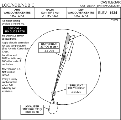
Coffin corner for one of the Castlegar approaches appears above—an airport notorious for special considerations. As with all instrument approach plates, the notations that appear here have to be included in the approach plate briefing. Many of the Castlegar notions are unique to this airport, but a good portion of the notations are standard and appear on many approach plates.
Pressure Considerations and Temperature Corrections
An altimeter setting is considered current up to 90 minutes from the time of observation, but care must be exercised when using an altimeter setting that is older than 60 minutes, or when the pressure is reported as falling rapidly.
Where remote altimeter setting are authorised for an approach procedure, the authorisation is also usually accompanied by a correction value. When conducting the approach at Langley Airport when the Tower is closed, for example, the Abbotsford altimeter setting is used and 50’ must be added to all altitudes. This requirement appears in the coffin corner of this approach plate. A similar requirement is specified for the NDB and GPS approaches at Nanaimo Airport.
If a remote altimeter setting is permanently prescribed in the published procedure—the Qualicum Beach GPS 29 is an example of this—the correction figure is incorporated into the published altitudes.
With respect to temperature corrections, a Cold Temperature Corrections Table (below) is published both in the AIP (RAC Fig. 9.1), and in the General Pages of the Canada Air Pilot; this table prescribes values to be added to the published altitude values for a procedures. These values must be added whenever the temperature is below 0° C.
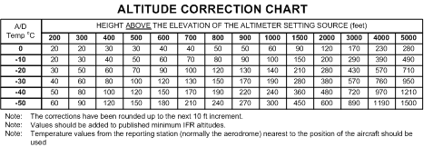
Both the remote pressure and the cold temperature values to be added must be applied to all published procedure altitudes, including minimum sector altitudes and DME arcs in order to ensure adequate obstacle clearance.
Importantly, the pressure and temperature corrections do not apply to ATC-assigned altitudes or vectored altitudes.2
Whenever altitude corrections are applied to published final approach fix crossing altitudes, procedure turn or missed approach altitudes, pilots should advise ATC how much correction is to be applied.3
1 An example of this is where the approach facility such as an NDB or VOR is located at the airport.
2 A pilot may accept or refuse an IFR-assigned altitude base on assessment of the effects of temperature on obstacle clearance.
3 It would be quite awkward and impractical for the pilot to review each altitude correction individually—the values applied vary with the height of each published figure above the elevation of the altimeter source. Instead, the pilot could simply advise ATC—“corrections will be applied -10°C.”