IFR EN ROUTE AND HOLDS—RULES AND PROCEDURES
En Route
Position Reporting
The pilot of an IFR or controlled VFR flight is required to make position reports over any compulsory reporting points specified on IFR charts, and also over any other reporting point specified by ATC.1
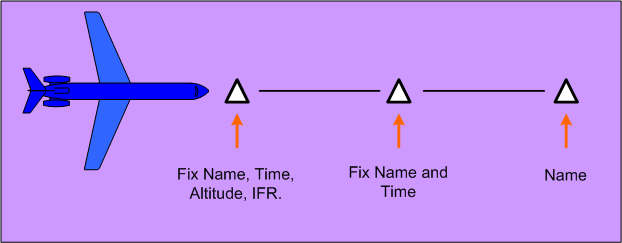
The position report shall include the following:
-
- the identification of the aircraft;
- the identification of the position;
- the time over the reporting point in UTC;
- the altitude or flight level;
- the type of flight plan or flight itinerary filed;
- the name of the next reporting point and the ETA over that point in UTC;
- the name only of the next succeeding reporting point along the route of flight; and
- any additional information requested by ATC or deemed necessary by the pilot.
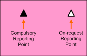
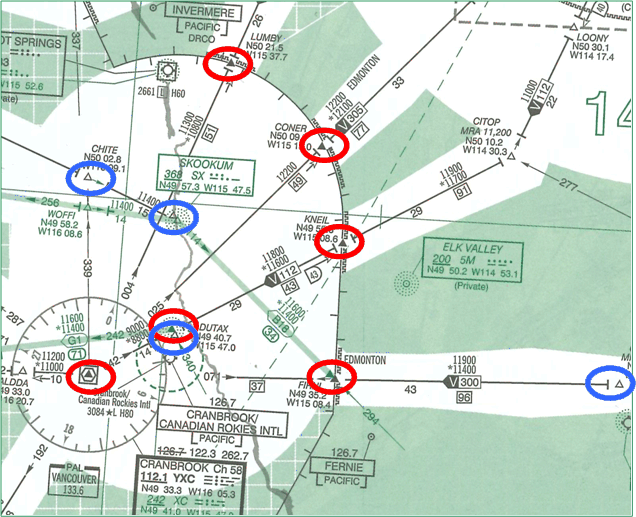
It should be noted that the compulsory reporting points are depicted on charts as solid triangles, while “on request” reporting points are open triangles. Obviously, position reporting over the latter are not made unless requested by ATC.
A second note concerning position reports is that compulsory position reporting is not to be done once an aircraft has been “radar identified” by ATC. Pilots will be advised by ATC when to resume normal position reporting practices.
Finally, if the estimated time for the next applicable reporting point is found to be in error in excess three minutes from that advised to ATC, a revised estimated time should be reported as soon as possible.
Mach Number Clearances and Reports
Clearances on turbojet aircraft may include a specified Mach number. If the Mach number cannot be conformed with, ATC must be informed when the clearance is issued. If, after acceptance, a Mach number cannot be conformed with, ATC must be notified as soon as possible. Where a Mach number is specified in a clearance, the Mach number must be included in each position report.
True Airspeed Requirements
ATC shall be notified as soon as practicable of any intended change in the TAS contained in an IFR flight plan or flight itinerary which is greater than 5%.
Climbs and Descents
When an altitude clearance is issued, the pilot must begin climbing or descending promptly once the clearance is acknowledged.
Additionally, the climb or descent should be made at an optimum rate that is consistent with the operating characteristic of the aircraft—if the pilot is unable to conform to these rates, or if the climb or descent is interrupted, the pilot must advise ATC.
The expression “at pilot’s discretion” is used by ATC in conjunction with an altitude clearance to mean that the change in altitude may be initiated when the pilot decides. When the change is initiated subsequently by the pilot, the pilot will advise ATC. Similarly, ATC must be advised if the subsequent change in altitude is interrupted.
Visual Climbs and Descents
There are two categories of visual climbs and descents, the first concerns the pilot’s visual separation from other aircraft, and the second concerns the pilot’s visual separation from terrain and obstacles.
With respect to climbs or descents that entail visual separation from other aircraft, these may only be authorised by ATC when VMC conditions prevail and when requested by the pilot. Additionally, they can be authorised in radar or non-radar environments, but they cannot be conducted or authorised in Class A or B airspace.
In contrast, climbs or descents that entail visual separation from terrain and obstacles can be either requested by the pilot or suggested by the controller. Such climbs or descents are restricted to a radar environment during a radar-vectoring phase. Note that ATC will continue to provide separation from other IFR aircraft.
Minimum IFR Altitudes
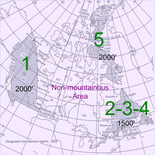
Except when taking off or landing, an IFR aircraft shall be operated at 1000’ from the highest obstacle within a horizontal distance of 5 NM.
There are two exceptions to this—the first is when the aircraft is operated within a Designated Mountainous Areas (DMAs), and the second is when aircraft are operating in areas for which minimum IFR altitudes have been established.
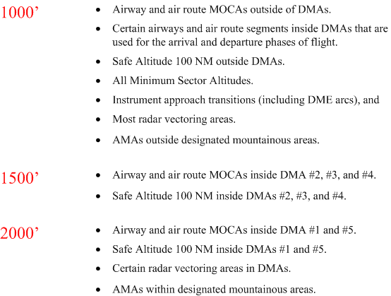
Minimum IFR altitudes are therefore categorised into one of the following:
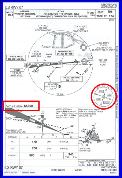
Below is an example of the published Safe 100 NM Altitude, and the Minimum Sector Altitude:
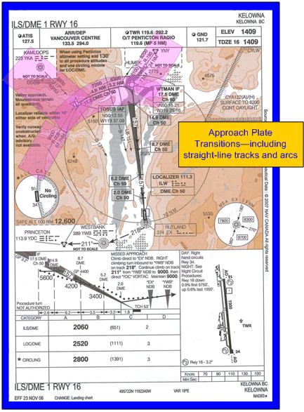
Below is an example of the published transitions associated with an approach plate:
MEAs and MOCAs
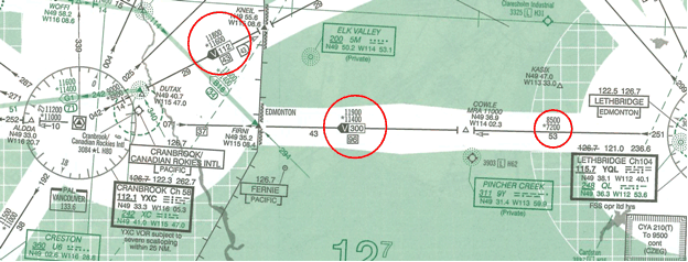
Minimum En Route Altitude (MEA) is defined as the published minimum altitude ASL between specified fixes on airways and air routes which ensures acceptable navigational signal coverage and which meets the IFR obstacle clearance requirements. There is noposted next to MEAs.
The minimum flight plan altitude shall be the nearest altitude or flight level consistent with the direction of flight that is at or above the MEA.
Since MEAs are likely different for segments on either side of a fix, aircraft shall in all cases cross the fix at the higher MEA.
In contrast, the Minimum Obstruction Clearance Altitude (MOCA) is defined as that altitude between fixes on low level airways that meet the IFR obstruction clearance requirements for the route segment. MOCA are indicated by an asterisk (*), representing an airplane splat.
MEA is always higher than MOCA, but MOCA is only published when different from MEA.
The MOCA, or the MEA when the MOCA is not published, is the lowest altitude for the airway or air route segment at which IFR flight may occur, and are published for emergency purposes—e.g., an engine failure or icing conditions.
The MOCA or MEA published value is based on ICAO standard atmosphere conditions (ISA).
Special Note: Since MOCA and MEA are based on ISA, extreme caution must be used when air temperatures are much lower than ISA, and in such cases aircraft should be operated at altitudes at least 1000’ above the MEA or MOCA.
Equal caution must be used when flying in an area of low pressure where the true altitude will always be lower than the corresponding flight level.
Pressure errors, combined with temperature error, can produce an overall true altitude error in excess of 2000’.
Mountain waves, combined with extremely low temperatures, could make the altimeter over-read by as much as 3000’.
MRAs
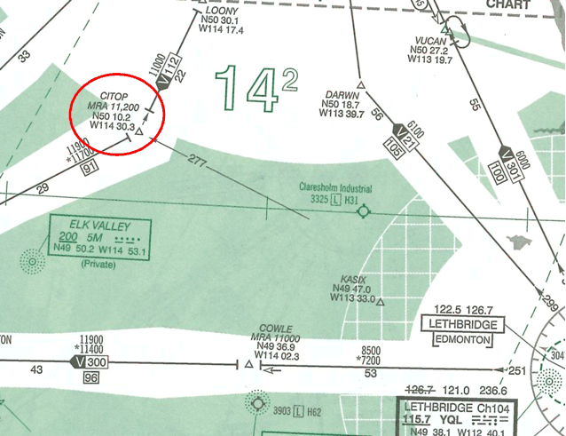
Minimum Reception Altitudes (MRAs) are sometimes published for intersections where the minimum altitude at which the VHF/UHF signal can be received is higher than the MEA for the segment in which the intersection is located.
ATC Altitude Assignment
In controlled airspace, ATC is not permitted to approve or assign any IFR altitude below the minimum IFR altitude.
Altitudes below MEA, but not below MOCA, may be approved by ATC when specifically requested by the pilot in the interests of flight safety—e.g., due to icing conditions.
ATC may assign an altitude that is not appropriate for the direction of flight along an airway if the request is made by the pilot owing to icing, turbulence, or fuel considerations.2
1000’-on-Top (IFR)
The provision to operate 1000’-on-top exists so that separation restrictions normally applied by ATC can be temporary suspended. An aircraft cleared to operate 1000’-on-top provides its own separation for other IFR aircraft—especially useful when two aircraft are transitioning to or from an approach when VFR conditions exist above cloud layers.
1000’-on-top can be conducted provided the following conditions exists:
- flight is maintained at least 1000’ above all cloud, haze, smoke, or other formations;
- flight visibility is at least 3 SM;
- the tops of formations are clearly defined;
- the level of flight appropriate to direction is maintained when in level flight;
- ATC authorisation is provided;
- the flight is conducted in Classes B, C, D, or E airspace.
Clearances to enter or leave Controlled Airspace
ATC will use the phrase “while in controlled airspace,” and will specify the altitude to exit or enter controlled airspace, and will also specify the lateral position at which the transition is to be conducted if required.
The altitude specified for entry or exit need only be the minimum safe IFR altitude for the applicable controlled airspace.
Clearance Limit
The clearance limit of an aircraft is the point to which an IFR aircraft is cleared.
While further clearance is normally provided before an aircraft reaches its limit, in cases where the clearance limit is inadvertently reached, the pilot shall hold at the clearance limit and request further clearance.
It is the pilot’s responsibility to ensure a clearance received can be safely complied with in the event of a communications failure.
IFR in Uncontrolled Airspace
When operating in uncontrolled airspace pilots should continuously monitor 126.7 MHz. whenever practicable.
A position report should be made when crossing navigation aids along a route of flight; the reports should be direct to the nearest ground station, and should be repeated on 126.7 MHz whenever possible.3 The report should include present position, track, altitude, altimeter setting in use, next position to be reported and the associated ETA.
Intentions should also be broadcast on 126.7 MHz prior to every altitude change, prior to commencing an instrument approach, or prior to an IFR departure; such broadcasts should be sufficiently detailed so as to enable other pilots to determine potential conflicts.
Where an MF is designated for airport, arriving pilots shall first broadcast their intentions on 126.7 MHz before changing to the MF frequency.
Holds and Holding Procedures
The hold entries and manoeuvres specified in AIM4 must be adhered. Through adherence, the airspace to be protected by ATC during a hold clearance can be maintained.
Hold Clearance Format
ATC: "ABC, hold clearance when you are ready to copy."
Pilot: "Go ahead with clearance, ABC."
ATC: "ABC is cleared to the Whatcom VORTAC via direct, to hold southwest, inbound on the 230° Radial. Maintain 4000, and expect further clearance at 2130.”
Pilot: "ABC is cleared to the Whatcom VORTAC via direct, to hold southwest, inbound on the 230° Radial. Maintain 4000, and expect further clearance at 2130.
ATC: "ABC, you read-back is cor
A hold clearance contains the following components:
- clearance to the holding fix;
- direction to hold from the holding fix;
- a specified radial, course, or inbound track that is used for the hold;
- the DME to be used, if applicable;
- the altitude or flight level to be maintained;
- the time at which further clearance or approach clearance is to be expected (in the event of a communications failure.)
During hold entries and hold manoeuvring, the pilot shall make all turns so as to achieve an average angle of bank of 25°, or a rate of turn of 3° per second, whichever requires the lesser bank.
Unless otherwise specified by ATC or specified by a published hold depiction contained on an IFR chart or plate, the pilot shall make all turns in the hold to the right—excepting the initial turns conducted during the hold entry.
In the event that a clearance limit is reached prior to obtaining further clearance from ATC, the pilot shall hold as published on a chart of plate. In the event that a hold is not published for the clearance limit, the pilot shall hold in a standard pattern in the inbound track to the clearance limit fix.
Hold Anatomy
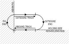
As depicted above, a hold is anchored on a fix based on an assigned inbound track (whether an NDB track, a VOR radial, or an airway). There is a fix end and outbound end on a hold, and there is also an inbound leg and outbound leg.
Standard Holding Pattern
The standard holding pattern is described in the AIM as follows:
Having entered the holding pattern, on the second and subsequent arrivals over the fix, the pilot executes a right turn to fly an outbound track that positions the aircraft most appropriately for the turn onto the inbound track. When holding at a VOR, pilots should begin the turn to the outbound leg at the time of station passage as indicated on the TO-FROM indicator. (The aircraft shall continue) . . inbound for 1 minute if at or below 14000 feet ASL, or 1 ½ minutes if above 14000’ ASL (AIM, RAC, Section 10.3).
Non-standard Holding Pattern
A non-standard holding pattern is the same as a standard hold, except that all turns are made to the left.5
Hold Entries
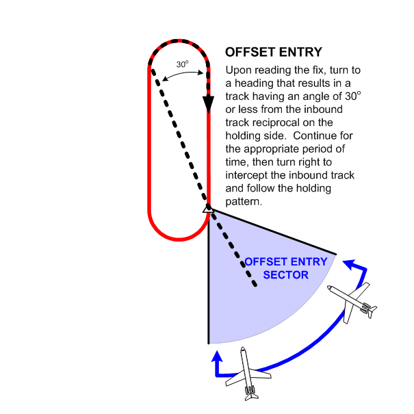
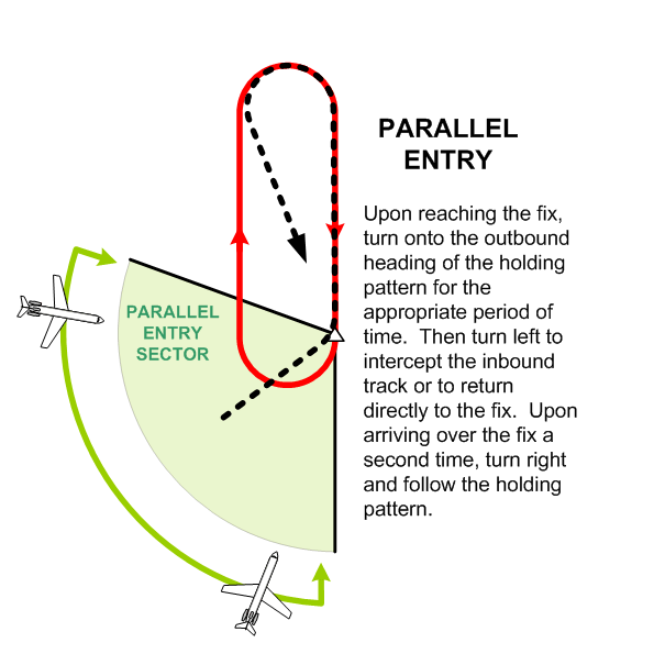
The entry into holding patterns is specified and must be adhered to. There are three types of hold-entries, referred to as the direct entry, offset entry, and the parallel entry.
The type of hold entry flown depends on two factors—the position of the aircraft relative to the fix on which the hold has been assigned, and the specific radial or inbound track that is assigned in the hold.
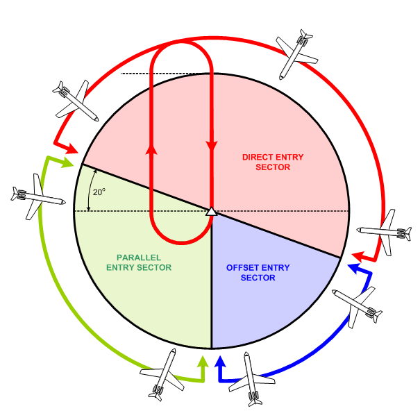
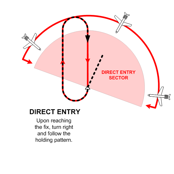
The hold-entry sectors are depicted below. In this diagram, the aircraft have been assigned to hold north of the fix. If the fix were a VOR, the hold is assigned on the 360° Radial; if the fix were an NDB, the hold would be assigned inbound on the 180° Track. As is shown, all aircraft approaching the fix from the north (within the sector shown) would perform a direct entry. Similarly, aircraft approaching from the south-east (again from within the sector) would perform an offset entry, and aircraft approaching from the south-west (relative to the sector) would perform a parallel entry.
The POD Method for Determining Hold Entry
IFR pilots must utilise a practical method of quickly determining the type of entry that must be flown. There are a few minor variations on the technique used, but all incorporate what is referred to as the “POD” method of hold entry recognition.
The POD method is based on the pilot visually positioning the hold entry sectors on the HSI display when the aircraft is proceeding directly the fix on which a hold has been assigned. Here is what the pilot visualises:
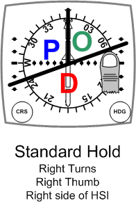
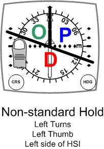
Once the above sectors are visualised on the HSI (or HI), the application is simple—but you want to get it right: once the aircraft is established direct to the fix (as the above depictions indicate), plug in the outbound track associated with assigned hold. Thus, for example, in the case of the depictions above, showing what the pilot sees when tracking to the assigned fix, a clearance for a standard hold on the 300° Radial will require a parallel entry—cross the fix and turn left to track outbound on the 300° Radial, and then make a left turn and proceed directly to the fix (parallel entries require an “opposite turn” (opposite to the right turns associated with a standard hold, or opposite to left turns associated with a non-standard hold). Similarly, a clearance for a standard hold on the 040° Radial will require an offset entry—cross the fix and turn slightly right to track outbound on the 010° Radial, and then make a right turn to intercept the 040° Radial inbound to the fix. Direct entries are considered the easiest—if the standard hold is assigned on the 150° Radial, cross the fix and turn to a heading of 150°, and after flying one minute outbound, turn right to intercept the 150° Radial inbound to the fix. Here are some sample hold clearances and entries:
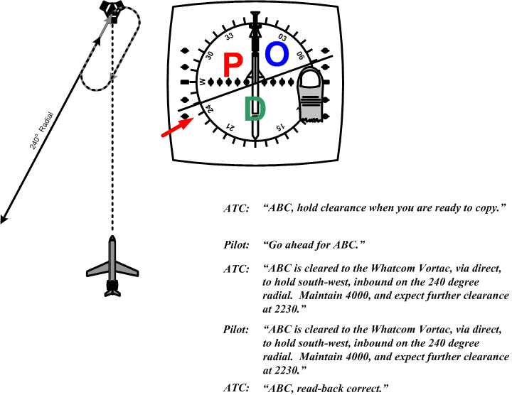
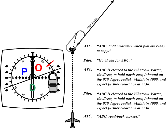
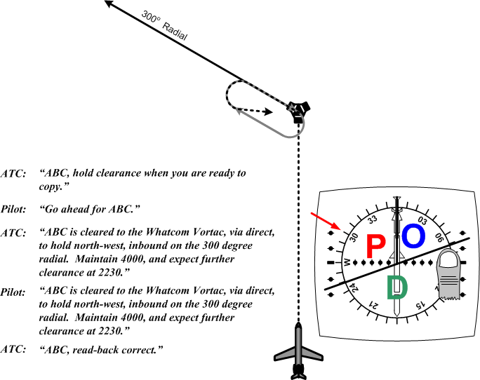
In the case of non-standard holds, things are reversed. A clearance for a hold on the 300° Radial will require an offset entry—cross the fix and turn to track outbound on the 330° Radial (300°+30°), after which a left turn is required to intercept the 300° Radial inbound. A parallel entry—say a hold on the 040° Radial—requires an “opposite” right turn to proceed directly to the fix after flying outbound on the 040° Radial for one minute. Finally, a direct entry into a non-standard hold requires simply that left turns be established.
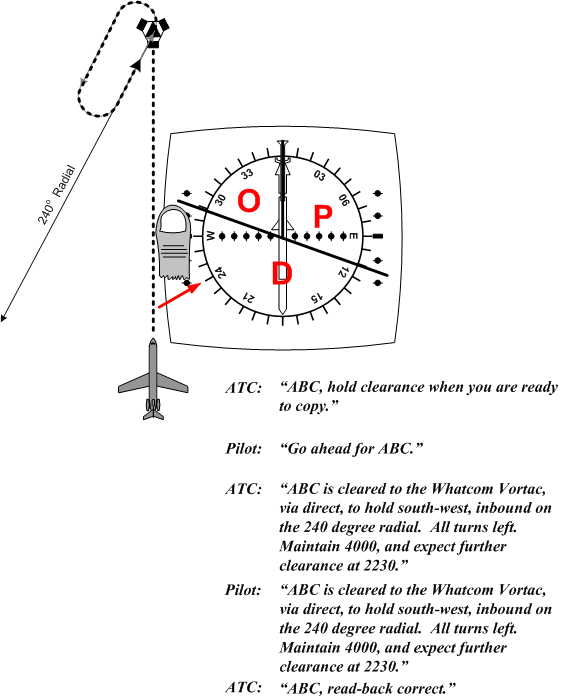
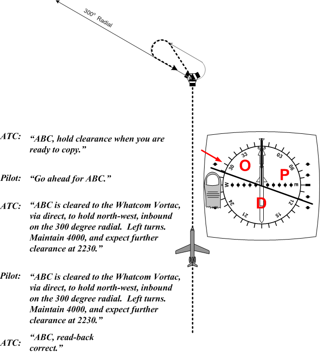
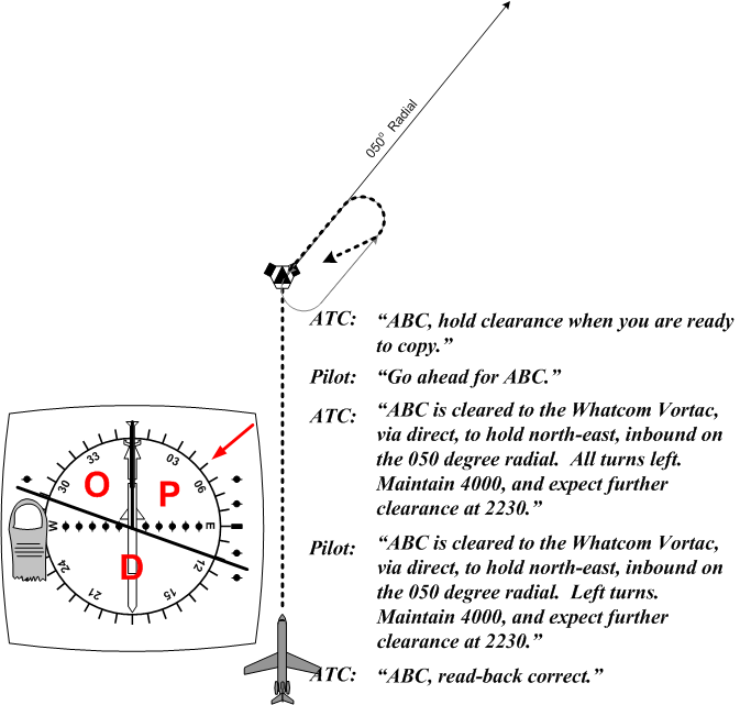
Caution must be exercised when complying with a clearance to hold on an NDB, as the hold will be assigned based on the inbound track. If you plug in the inbound track to the POD display, you will get it muddled—to have to figure out the reciprocal outbound heading.
Hold Timing
The time requirement for a hold mentioned above—1 minute for holds at or below 14000’ and 1-½ minutes for holds above this level—refer to the time of the inbound leg of a hold. Whatever the wind conditions, this is the standard that has to be met when flying a hold. Adjustments with respect to both heading—to correct for wind drift—and time—to compensate for ground speed—must therefore be made to the outbound leg. The pilot, therefore, must adjust the outbound leg—time and heading—to affect the time targets for the inbound leg. With respect to heading adjustments, the rule commonly applied is the wind drift heading adjustment on the inbound leg should be double on the outbound leg—if a 10° wind drift correction angle is applied to the left to maintain track during the inbound leg, this must be double during the outbound leg—i.e., a 20° wind drift correction angle applied to the right. The adjustment of time is more straightforward—if the inbound leg is initially timed at 50 seconds (in the case of 1-minute holds) after flying a 1 minute outbound leg, the outbound leg should be increased by 10 seconds.
DME Holds
A DME hold can be specified whereby an aircraft is cleared to hold between to DME distances—typically separated by 5 NM.
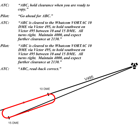
A DME hold clearance is provided while the aircraft is tracking inbound or outbound on a VOR/VORTAC radial.
Note, in the depiction above, that an aircraft northeast bound on V495 (lower left to upper right) would perform a direct entry into the hold, while a southwest bound aircraft would perform a parallel or offset entry—likely the former, since it would be the easier with respect to position reckoning.
Holding Speed Limits
Speed limits govern holding procedures. For propeller aircraft, including turboprop aircraft, the maximum speed is 175 KIAS. In the case of turbojet aircraft, the maximum speed is 230 KIAS at or below 14000’, and 265 KIAS above 14000’.
Shuttle Procedures
The procedures that are used during holds are also used during shuttle manoeuvres where a climb or descent is undertaken while conducting a holding pattern over a fix—very commonly required during instrument departures and arrivals in mountainous areas. Here is what the AIM has to say:
A shuttle procedure is defined as a manoeuvre involving a descent or climb in a pattern resembling a holding pattern. Shuttles are generally prescribed on instrument procedures located in mountainous areas. In the approach phase, it is normally prescribed where a descent of more than 2000 feet is required during the initial or intermediate approach segments. It can also be required when flying a missed approach or departure procedure from certain airports. A shuttle procedure shall be executed in the pattern as published unless instructions contained in an ATC clearance direct otherwise.6
A speed limit of 200 KIAS applies to shuttle manoeuvres.
References
1 Position reporting is not compulsory after an aircraft has been radar identified.
2 The reference here to “fuel considerations” is specifically limited to situations in which the pilot wishes to avoid an otherwise unnecessary fuel stop prior to reaching the destination airport, and should not be confused with “fuel efficiency.”
3 When the report is made on a frequency other than 126.7, the report should be repeated over 126.7 to alert other aircraft in the area.
4 Section 10.0 (Instrument Flight Rules—Holding Procedures) of AIM RAC.
5 A hold is also considered non-standard when the time components vary from the minute or 1 ½ minute requirements specified for standard holds.
.jpg)

